B10011S
2. Pin Configuration
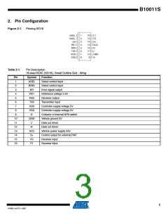
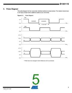
Figure 2-1. Pinning SO16
1
2
3
4
5
6
7
8
16
15
ASEL
BSEL
ER
RX1
RX0
TX0
F1
F0
14 S+
13
VCC
12 H'
11
L'
10
9
VDD
VSS
GND
S-
Table 2-1.
Pin Description
16-lead SOIC (SO16), Small Outline Gull - Wing
Pin
1
Symbol
ASEL
BSEL
ER
Function
Select control input
Select control input
Error signal output
Reference voltage 2.5V
Receiver output
2
3
4
RX1
RX0
TX0
VDD
VSS
S-
5
6
Transmitter input
7
Controller supply voltage 5V
Controller supply voltage 0V
Collector of internal NPN switch
Vehicle ground 0V
8
9
10
11
12
13
14
15
16
GND
L’
Data out driver
H’
Data out driver
VCC
S+
Vehicle power supply 24V
Control output for external PNP
Receiver input
F0
F1
Receiver input
3
4749D–AUTO–10/07

 ATMEL [ ATMEL ]