ATmega64A
14. 8-bit Timer/Counter0 with PWM and Asynchronous Operation
14.1 Features
• Single Channel Counter
• Clear Timer on Compare Match (Auto Reload)
• Glitch-free, Phase Correct Pulse Width Modulator (PWM)
• Frequency Generator
• 10-bit Clock Prescaler
• Overflow and Compare Match Interrupt Sources (TOV0 and OCF0)
• Allows Clocking from External 32 kHz Watch Crystal Independent of the I/O Clock
14.2 Overview
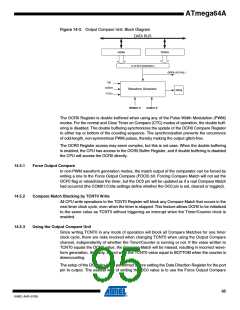
Timer/Counter0 is a general purpose, single-channel, 8-bit Timer/Counter module. A simplified
block diagram of the 8-bit Timer/Counter is shown in Figure 14-1. For the actual placement of
I/O pins, refer to “Pin Configuration” on page 2. CPU accessible I/O Registers, including I/O bits
and I/O pins, are shown in bold. The device-specific I/O Register and bit locations are listed in
the “Register Description” on page 106.
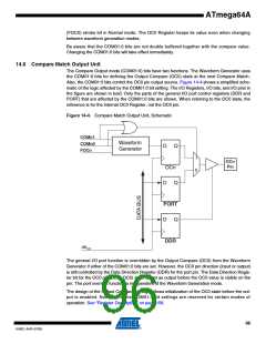
Figure 14-1. 8-bit Timer/Counter Block Diagram.
TCCRn
count
TOVn
(Int. Req.)
clear
Control Logic
TOP
direction
clkTn
TOSC1
TOSC2
BOTTOM
T/C
Oscillator
Prescaler
Timer/Counter
TCNTn
= 0
= 0xFF
clkI/O
OCn
OCn
(Int. Req.)
Waveform
Generation
=
OCRn
clkI/O
Synchronized Status Flags
Synchronization Unit
clkASY
Status Flags
ASSRn
Asynchronous Mode
Select (ASn)
Registers
92
8160C–AVR–07/09

 ATMEL [ ATMEL ]