ATmega16/32/64/M1/C1
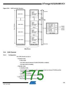
Figure 16-5. CAN Controller Structure
Low priority
Control
Status
IDtag+IDmask
Time Stamp
Buffer MOb i
MOb i
MOb
Scanning
Control
Status
IDtag+IDmask
Time Stamp
Gen. Control
Gen. Status
Enable MOb
Interrupt
Buffer MOb2
Buffer MOb1
LCC
MAC
PLS
Internal
TxCAN
MOb2
Internal
RxCAN
Bit Timing
Line Error
CAN Timer
Control
Status
IDtag+IDmask
Time Stamp
CAN Channel
MOb1
Control
Status
IDtag+IDmask
Time Stamp
Buffer MOb0
MOb0
High priority
CAN Data Buffers
Message Objets
Mailbox
16.4 CAN Channel
16.4.1
Configuration
The CAN channel can be in:
• Enabled mode
In this mode:
– the CAN channel (internal TxCAN & RxCAN) is enabled,
– the input clock is enabled.
• Standby mode
In standby mode:
– the transmitter constantly provides a recessive level (on internal TxCAN) and the
receiver is disabled,
– input clock is enabled,
– the registers and pages remain accessible.
• Listening mode
This mode is transparent for the CAN channel:
175
7647F–AVR–04/09

 ATMEL [ ATMEL ]