ATmega16/32/64/M1/C1
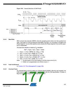
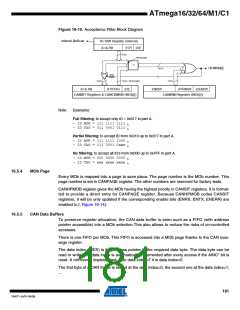
Figure 16-8. General Structure of a Bit Period
1
/
CLK
IO
CLK
IO
Bit Rate Prescaler
Tscl (TQ)
F
CAN
one nominal bit
Data
Tsyns(5)
Tprs
Tphs1 (
or
Tphs1+Tsjw (
1
)
Tphs2 (
or
Tphs2+Tsjw (4)
2)
Notes: 1. Phase error < 0
2. Phase error > 0
3
)
3. Phase error > 0
4. Phase error < 0
5. Synchronization Segment: SYNS
Tbit
Tsyns=1 Tscl (fixed
x
)
Sample
Point
Transmission
Point
16.4.3
Baud Rate
With no baud rate prescaler (BRP[5..0]=0) the sampling point comes one time quantum too
early. This leads to a fail according the ISO16845 Test plan. It is necessary to lengthen the
Phase Segment 1 by one time quantum and to shorten the Phase Segment 2 by one time quan-
tum to compensate.
The baud rate selection is made by T calculation:
bit
Tbit(1) = Tsyns + Tprs + Tphs1 + Tphs2
1. Tsyns = 1 x Tscl = (BRP[5..0]+ 1)/clkIO (= 1TQ)
2. Tprs = (1 to 8) x Tscl = (PRS[2..0]+ 1) x Tscl
3. Tphs1 = (1 to 8) x Tscl = (PHS1[2..0]+ 1) x Tscl
4. Tphs2 = (1 to 8) x Tscl = (PHS2[2..0](2)+ 1) x Tscl
5. Tsjw = (1 to 4) x Tscl = (SJW[1..0]+ 1) x Tscl
Notes: 1. The total number of Tscl (Time Quanta) in a bit time must be from 8 to 25.
2. PHS2[2..0] 2 is programmable to be ≤PHS1[2..0] and ≥ 1.
16.4.4
16.4.5
Fault Confinement
(c.f. Section 16.7 “Error Management” on page 183).
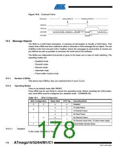
Overload Frame
An overload frame is sent by setting an overload request (OVRQ). After the next reception, the
CAN channel sends an overload frame in accordance with the CAN specification. A status or
flag is set (OVRF) as long as the overload frame is sent.
177
7647F–AVR–04/09

 ATMEL [ ATMEL ]