14.9 PSC Input
For detailed information on the PSC, please refer to Application Note ‘AVR138: PSC Cookbook’,
available on the Atmel web site.
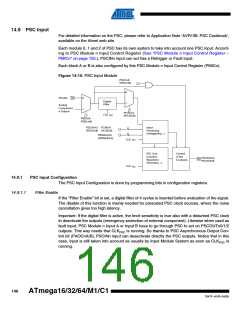
Each module 0, 1 and 2 of PSC has its own system to take into account one PSC input. Accord-
ing to PSC Module n Input Control Register (See “PSC Module n Input Control Register –
PMICn” on page 155.), PSCINn input can act has a Retrigger or Fault input.
Each block A or B is also configured by this PSC Module n Input Control Register (PMICn).
Figure 14-10. PSC Input Module
PAOCnA
(PAOCnB)
0
PSCINn
0
1
Digital
Filter
1
Analog
Comparator
n Output
PFLTEnA
(PFLTEnB)
CLK
PSC
PISELnA
(PISELnB)
PELEVnA / PCAEnA
(PELEVnB) (PCAEnB)
Input
Processing
(retriggering ...)
2
4
PRFMnA3:0
(PRFMnB3:0)
CLK
PSC
PSC Core
(Counter,
Control
of the
PSCOUTnA
PSCOUTnB
Waveform
Generator, ...)
6 outputs
CLK
PSC
14.9.1
PSC Input Configuration
The PSC Input Configuration is done by programming bits in configuration registers.
14.9.1.1
Filter Enable
If the “Filter Enable” bit is set, a digital filter of 4 cycles is inserted before evaluation of the signal.
The disable of this function is mainly needed for prescaled PSC clock sources, where the noise
cancellation gives too high latency.
Important: If the digital filter is active, the level sensitivity is true also with a disturbed PSC clock
to deactivate the outputs (emergency protection of external component). Likewise when used as
fault input, PSC Module n Input A or Input B have to go through PSC to act on PSCOUTn0/1/2
outputs. This way needs that CLKPSC is running. So thanks to PSC Asynchronous Output Con-
trol bit (PAOCnA/B), PSCINn input can desactivate directly the PSC outputs. Notice that in this
case, input is still taken into account as usually by Input Module System as soon as CLKPSC is
running.
146
ATmega16/32/64/M1/C1
7647F–AVR–04/09

 ATMEL [ ATMEL ]