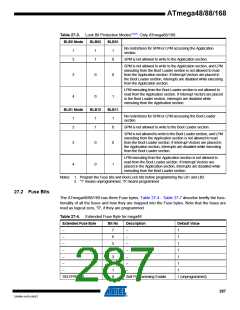
Table 27-5. Extended Fuse Byte for mega88/168
Extended Fuse Byte
Bit No
Description
Default Value
–
–
–
–
–
7
6
5
4
3
–
–
–
–
–
1
1
1
1
1
Select Boot Size
(see Table 26-6 on page 282
and Table 26-9 on page 283
for details)
BOOTSZ1
2
0 (programmed)(1)
Select Boot Size
(see Table 26-6 on page 282
and Table 26-9 on page 283
for details)
BOOTSZ0
BOOTRST
1
0
0 (programmed)(1)
1 (unprogrammed)
Select Reset Vector
Note:
1. The default value of BOOTSZ1..0 results in maximum Boot Size. See Table 27-11 on page
291 for details.
Table 27-6. Fuse High Byte
High Fuse Byte
RSTDISBL(1)
DWEN
Bit No
Description
Default Value
7
6
External Reset Disable
debugWIRE Enable
1 (unprogrammed)
1 (unprogrammed)
Enable Serial Program and
Data Downloading
0 (programmed, SPI
programming enabled)
SPIEN(2)
5
4
WDTON(3)
Watchdog Timer Always On
1 (unprogrammed)
EEPROM memory is
preserved through the Chip
Erase
1 (unprogrammed), EEPROM
not reserved
EESAVE
3
Brown-out Detector trigger
level
BODLEVEL2(4)
BODLEVEL1(4)
BODLEVEL0(4)
2
1
0
1 (unprogrammed)
1 (unprogrammed)
1 (unprogrammed)
Brown-out Detector trigger
level
Brown-out Detector trigger
level
Notes: 1. See “Alternate Functions of Port C” on page 82 for description of RSTDISBL Fuse.
2. The SPIEN Fuse is not accessible in serial programming mode.
3. See “WDTCSR – Watchdog Timer Control Register” on page 54 for details.
4. See Table 28-4 on page 308 for BODLEVEL Fuse decoding.
288
ATmega48/88/168
2545M–AVR–09/07

 ATMEL [ ATMEL ]