ATmega48/88/168
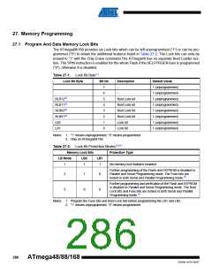
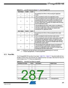
Table 27-3. Lock Bit Protection Modes(1)(2). Only ATmega88/168.
BLB0 Mode
BLB02
BLB01
No restrictions for SPM or LPM accessing the Application
section.
1
2
1
1
1
0
SPM is not allowed to write to the Application section.
SPM is not allowed to write to the Application section, and LPM
executing from the Boot Loader section is not allowed to read
from the Application section. If Interrupt Vectors are placed in
the Boot Loader section, interrupts are disabled while executing
from the Application section.
3
4
0
0
0
1
LPM executing from the Boot Loader section is not allowed to
read from the Application section. If Interrupt Vectors are placed
in the Boot Loader section, interrupts are disabled while
executing from the Application section.
BLB1 Mode
BLB12
BLB11
No restrictions for SPM or LPM accessing the Boot Loader
section.
1
2
1
1
1
0
SPM is not allowed to write to the Boot Loader section.
SPM is not allowed to write to the Boot Loader section, and LPM
executing from the Application section is not allowed to read
from the Boot Loader section. If Interrupt Vectors are placed in
the Application section, interrupts are disabled while executing
from the Boot Loader section.
3
4
0
0
0
1
LPM executing from the Application section is not allowed to
read from the Boot Loader section. If Interrupt Vectors are
placed in the Application section, interrupts are disabled while
executing from the Boot Loader section.
Notes: 1. Program the Fuse bits and Boot Lock bits before programming the LB1 and LB2.
2. “1” means unprogrammed, “0” means programmed
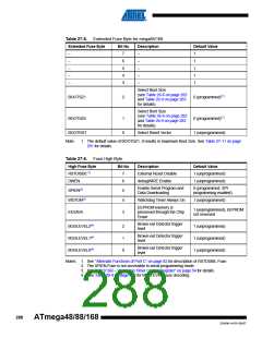
27.2 Fuse Bits
The ATmega48/88/168 has three Fuse bytes. Table 27-4 - Table 27-7 describe briefly the func-
tionality of all the fuses and how they are mapped into the Fuse bytes. Note that the fuses are
read as logical zero, “0”, if they are programmed.
Table 27-4. Extended Fuse Byte for mega48
Extended Fuse Byte
Bit No
Description
Default Value
–
7
6
5
4
3
2
1
0
–
1
–
–
1
–
–
1
–
–
1
–
–
1
–
–
1
–
–
1
SELFPRGEN
Self Programming Enable
1 (unprogrammed)
287
2545M–AVR–09/07

 ATMEL [ ATMEL ]