27. Memory Programming
27.1 Program And Data Memory Lock Bits
The ATmega88/168 provides six Lock bits which can be left unprogrammed (“1”) or can be pro-
grammed (“0”) to obtain the additional features listed in Table 27-2. The Lock bits can only be
erased to “1” with the Chip Erase command.The ATmega48 has no separate Boot Loader sec-
tion. The SPM instruction is enabled for the whole Flash if the SELFPRGEN fuse is programmed
(“0”), otherwise it is disabled.
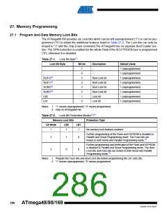
Table 27-1. Lock Bit Byte(1)
Lock Bit Byte
Bit No
Description
–
Default Value
7
6
5
4
3
2
1
0
1 (unprogrammed)
1 (unprogrammed)
1 (unprogrammed)
1 (unprogrammed)
1 (unprogrammed)
1 (unprogrammed)
1 (unprogrammed)
1 (unprogrammed)
–
BLB12(2)
Boot Lock bit
Boot Lock bit
Boot Lock bit
Boot Lock bit
Lock bit
BLB11(2)
BLB02(2)
BLB01(2)
LB2
LB1
Lock bit
Notes: 1. “1” means unprogrammed, “0” means programmed
2. Only on ATmega88/168.
Table 27-2. Lock Bit Protection Modes(1)(2)
Memory Lock Bits
Protection Type
LB Mode
LB2
LB1
1
1
1
No memory lock features enabled.
Further programming of the Flash and EEPROM is disabled in
Parallel and Serial Programming mode. The Fuse bits are
locked in both Serial and Parallel Programming mode.(1)
2
1
0
0
0
Further programming and verification of the Flash and EEPROM
is disabled in Parallel and Serial Programming mode. The Boot
Lock bits and Fuse bits are locked in both Serial and Parallel
Programming mode.(1)
3
Notes: 1. Program the Fuse bits and Boot Lock bits before programming the LB1 and LB2.
2. “1” means unprogrammed, “0” means programmed
286
ATmega48/88/168
2545M–AVR–09/07

 ATMEL [ ATMEL ]