Table 93. No. of Words in a Page and no. of Pages in the Flash
Flash Size
Page Size
PCWORD
No. of Pages
PCPAGE
PCMSB
4K words (8K bytes)
32 words
PC[4:0]
128
PC[11:5]
11
Table 94. No. of Words in a Page and no. of Pages in the EEPROM
EEPROM Size
Page Size
PCWORD
No. of Pages
PCPAGE
EEAMSB
512 bytes
4 bytes
EEA[1:0]
128
EEA[8:2]
8
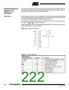
Parallel Programming
Enter Programming Mode
The following algorithm puts the device in Parallel Programming mode:
1. Apply 4.5 - 5.5V between VCC and GND, and wait at least 100 µs.
2. Set RESET to “0” and toggle XTAL1 at least 6 times
3. Set the Prog_enable pins listed in Table 90 on page 223 to “0000” and wait at
least 100 ns.
4. Apply 11.5 - 12.5V to RESET. Any activity on Prog_enable pins within 100 ns
after +12V has been applied to RESET, will cause the device to fail entering Pro-
gramming mode.
Note, if the RESET pin is disabled by programming the RSTDISBL Fuse, it may not be
possible to follow the proposed algorithm above. The same may apply when External
Crystal or External RC configuration is selected because it is not possible to apply qual-
ified XTAL1 pulses. In such cases, the following algorithm should be followed:
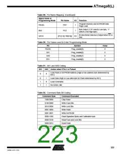
1. Set Prog_enable pins listed in Table 90 on page 223 to “0000”.
2. Apply 4.5 - 5.5V between VCC and GND simultaneously as 11.5 - 12.5V is
applied to RESET.
3. Wait 100 ns.
4. Re-program the fuses to ensure that External Clock is selected as clock source
(CKSEL3:0 = 0’b0000) and RESET pin is activated (RSTDISBL) unpro-
grammed). If Lock Bits are programmed, a chip erase command must be
executed before changing the fuses.
5. Exit Programming mode by power the device down or by bringing RESET pin to
0’b0.
6. Entering Programming mode with the original algorithm, as described above.
Considerations for Efficient
Programming
The loaded command and address are retained in the device during programming. For
efficient programming, the following should be considered.
•
•
•
The command needs only be loaded once when writing or reading multiple memory
locations.
Skip writing the data value 0xFF, that is the contents of the entire EEPROM (unless
the EESAVE Fuse is programmed) and Flash after a Chip Erase.
Address High byte needs only be loaded before programming or reading a new 256
word window in Flash or 256 byte EEPROM. This consideration also applies to
Signature bytes reading.
224
ATmega8(L)
2486M–AVR–12/03

 ATMEL [ ATMEL ]