ATmega8(L)
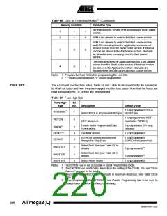
Table 88. Fuse Low Byte
Fuse Low
Byte
Bit
No.
Description
Default Value
BODLEVEL
BODEN
SUT1
7
6
5
4
3
2
1
0
Brown out detector trigger level
Brown out detector enable
Select start-up time
Select start-up time
Select Clock source
Select Clock source
Select Clock source
Select Clock source
1 (unprogrammed)
1 (unprogrammed, BOD disabled)
1 (unprogrammed)(1)
0 (programmed)(1)
SUT0
CKSEL3
CKSEL2
CKSEL1
CKSEL0
0 (programmed)(2)
0 (programmed)(2)
0 (programmed)(2)
1 (unprogrammed)(2)
Notes: 1. The default value of SUT1..0 results in maximum start-up time. SeeTable 10 on page
28 for details.
2. The default setting of CKSEL3..0 results in internal RC Oscillator @ 1MHz. See
Table 2 on page 24 for details.
The status of the Fuse Bits is not affected by Chip Erase. Note that the Fuse Bits are
locked if lock bit1 (LB1) is programmed. Program the Fuse Bits before programming the
Lock Bits.
Latching of Fuses
The fuse values are latched when the device enters Programming mode and changes of
the fuse values will have no effect until the part leaves Programming mode. This does
not apply to the EESAVE Fuse which will take effect once it is programmed. The fuses
are also latched on Power-up in Normal mode.
Signature Bytes
All Atmel microcontrollers have a 3-byte signature code which identifies the device. This
code can be read in both Serial and Parallel mode, also when the device is locked. The
three bytes reside in a separate address space.
For the ATmega8 the signature bytes are:
1. 0x000: 0x1E (indicates manufactured by Atmel).
2. 0x001: 0x93 (indicates 8KB Flash memory).
3. 0x002: 0x07 (indicates ATmega8 device).
Calibration Byte
The ATmega8 stores four different calibration values for the internal RC Oscillator.
These bytes resides in the signature row High byte of the addresses 0x000, 0x0001,
0x0002, and 0x0003 for 1, 2, 4, and 8 Mhz respectively. During Reset, the 1 MHz value
is automatically loaded into the OSCCAL Register. If other frequencies are used, the
calibration value has to be loaded manually, see “Oscillator Calibration Register – OSC-
CAL” on page 29 for details.
221
2486M–AVR–12/03

 ATMEL [ ATMEL ]