ATmega8(L)
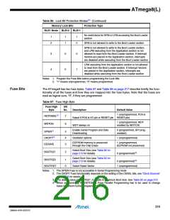
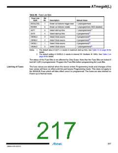
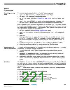
Table 88. Fuse Low Byte
Fuse Low
Byte
Bit
No.
Description
Default Value
BODLEVEL
BODEN
SUT1
7
6
5
4
3
2
1
0
Brown out detector trigger level
Brown out detector enable
Select start-up time
Select start-up time
Select Clock source
Select Clock source
Select Clock source
Select Clock source
1 (unprogrammed)
1 (unprogrammed, BOD disabled)
1 (unprogrammed)(1)
0 (programmed)(1)
SUT0
CKSEL3
CKSEL2
CKSEL1
CKSEL0
0 (programmed)(2)
0 (programmed)(2)
0 (programmed)(2)
1 (unprogrammed)(2)
Notes: 1. The default value of SUT1..0 results in maximum start-up time. See Table 10 on page 30 for
details
2. The default setting of CKSEL3..0 results in internal RC Oscillator @ 1MHz. See Table 2 on
page 26 for details
The status of the Fuse Bits is not affected by Chip Erase. Note that the Fuse Bits are locked if
lock bit1 (LB1) is programmed. Program the Fuse Bits before programming the Lock Bits.
Latching of Fuses
The fuse values are latched when the device enters Programming mode and changes of the
fuse values will have no effect until the part leaves Programming mode. This does not apply to
the EESAVE Fuse which will take effect once it is programmed. The fuses are also latched on
Power-up in Normal mode.
217
2486AA–AVR–02/2013

 ATMEL [ ATMEL ]