ATmega8(L)
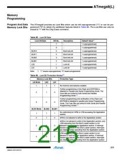
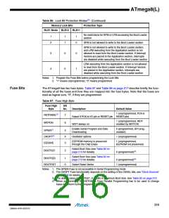
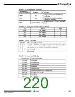
Table 86. Lock Bit Protection Modes(2) (Continued)
Memory Lock Bits
Protection Type
BLB1 Mode BLB12 BLB11
No restrictions for SPM or LPM accessing the Boot Loader
section
1
2
1
1
1
0
SPM is not allowed to write to the Boot Loader section
SPM is not allowed to write to the Boot Loader section,
and LPM executing from the Application section is not
allowed to read from the Boot Loader section. If Interrupt
Vectors are placed in the Application section, interrupts
are disabled while executing from the Boot Loader section
3
4
0
0
0
1
LPM executing from the Application section is not allowed
to read from the Boot Loader section. If Interrupt Vectors
are placed in the Application section, interrupts are
disabled while executing from the Boot Loader section
Notes: 1. Program the Fuse Bits before programming the Lock Bits
2. “1” means unprogrammed, “0” means programmed
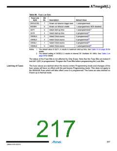
Fuse Bits
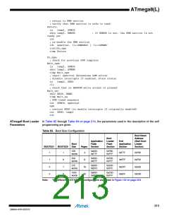
The ATmega8 has two fuse bytes. Table 87 and Table 88 on page 217 describe briefly the func-
tionality of all the fuses and how they are mapped into the fuse bytes. Note that the fuses are
read as logical zero, “0”, if they are programmed.
Table 87. Fuse High Byte
Fuse High
Byte
Bit
No.
Description
Default Value
1 (unprogrammed, PC6 is
Select if PC6 is I/O pin or RESET pin RESET-pin)
RSTDISBL(4)
7
6
1 (unprogrammed, WDT
enabled by WDTCR)
WDTON
WDT always on
Enable Serial Program and Data
Downloading
0 (programmed, SPI prog.
enabled)
SPIEN(1)
CKOPT(2)
EESAVE
5
4
3
Oscillator options
1 (unprogrammed)
EEPROM memory is preserved
through the Chip Erase
1 (unprogrammed,
EEPROM not preserved)
Select Boot Size (see Table 82 on
page 213 for details)
BOOTSZ1
2
0 (programmed)(3)
Select Boot Size (see Table 82 on
page 213 for details)
BOOTSZ0
BOOTRST
1
0
0 (programmed)(3)
1 (unprogrammed)
Select Reset Vector
Notes: 1. The SPIEN Fuse is not accessible in Serial Programming mode
2. The CKOPT Fuse functionality depends on the setting of the CKSEL bits, see “Clock Sources”
on page 26 for details
3. The default value of BOOTSZ1..0 results in maximum Boot Size. See Table 82 on page 213
4. When programming the RSTDISBL Fuse Parallel Programming has to be used to change
fuses or perform further programming
216
2486AA–AVR–02/2013

 ATMEL [ ATMEL ]