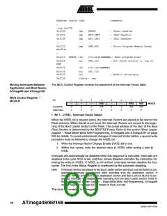
Address Labels Code
Comments
;
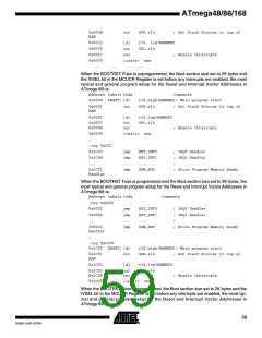
.org 0x1C00
0x1C00
0x1C02
0x1C04
...
jmp
jmp
jmp
...
jmp
RESET
; Reset handler
; IRQ0 Handler
; IRQ1 Handler
;
EXT_INT0
EXT_INT1
...
0x1C32
SPM_RDY
; Store Program Memory Ready
Handler
;
0x1C33 RESET: ldi
r16,high(RAMEND); Main program start
0x1C34
RAM
out
SPH,r16
; Set Stack Pointer to top of
0x1C35
ldi
r16,low(RAMEND)
SPL,r16
0x1C36
0x1C37
out
sei
; Enable interrupts
0x1C38
<instr> xxx
Moving Interrupts Between
Application and Boot Space,
ATmega88 and ATmega168
The MCU Control Register controls the placement of the Interrupt Vector table.
MCU Control Register –
MCUCR
Bit
7
–
6
–
5
–
4
3
–
2
–
1
IVSEL
R/W
0
0
IVCE
R/W
0
PUD
R/W
0
MCUCR
Read/Write
Initial Value
R
0
R
0
R
0
R
0
R
0
• Bit 1 – IVSEL: Interrupt Vector Select
When the IVSEL bit is cleared (zero), the Interrupt Vectors are placed at the start of the
Flash memory. When this bit is set (one), the Interrupt Vectors are moved to the begin-
ning of the Boot Loader section of the Flash. The actual address of the start of the Boot
Flash Section is determined by the BOOTSZ Fuses. Refer to the section “Boot Loader
Support – Read-While-Write Self-Programming, ATmega88 and ATmega168” on page
255 for details. To avoid unintentional changes of Interrupt Vector tables, a special write
procedure must be followed to change the IVSEL bit:
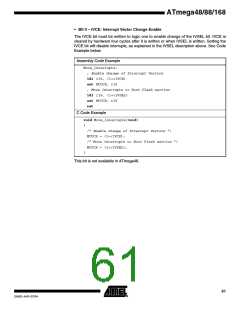
1. Write the Interrupt Vector Change Enable (IVCE) bit to one.
2. Within four cycles, write the desired value to IVSEL while writing a zero to
IVCE.
Interrupts will automatically be disabled while this sequence is executed. Interrupts are
disabled in the cycle IVCE is set, and they remain disabled until after the instruction fol-
lowing the write to IVSEL. If IVSEL is not written, interrupts remain disabled for four
cycles. The I-bit in the Status Register is unaffected by the automatic disabling.
Note:
If Interrupt Vectors are placed in the Boot Loader section and Boot Lock bit BLB02 is pro-
grammed, interrupts are disabled while executing from the Application section. If
Interrupt Vectors are placed in the Application section and Boot Lock bit BLB12 is pro-
gramed, interrupts are disabled while executing from the Boot Loader section. Refer to
the section “Boot Loader Support – Read-While-Write Self-Programming, ATmega88
and ATmega168” on page 255 for details on Boot Lock bits.
This bit is not available in ATmega48.
60
ATmega48/88/168
2545D–AVR–07/04

 ATMEL [ ATMEL ]