ATmega48/88/168
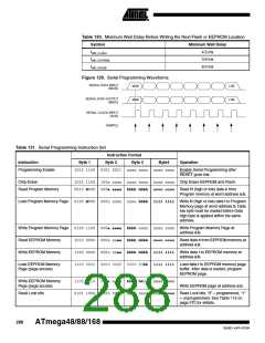
Table 131. Serial Programming Instruction Set (Continued)
Instruction Format
Byte 2 Byte 3
Instruction
Byte 1
Byte4
Operation
Write Lock bits
1010 1100 111x xxxx xxxx xxxx 11ii iiii Write Lock bits. Set bits = “0” to
program Lock bits. See Table 115 on
page 270 for details.
Read Signature Byte
Write Fuse bits
0011 0000 000x xxxx xxxx xxbb oooo oooo Read Signature Byte o at address b.
1010 1100 1010 0000 xxxx xxxx iiii iiii Set bits = “0” to program, “1” to
unprogram. See Table 121 on page
273 for details.
Write Fuse High bits
Write Extended Fuse Bits
Read Fuse bits
1010 1100 1010 1000 xxxx xxxx iiii iiii Set bits = “0” to program, “1” to
unprogram.See Table 120 on page
273 for details.
1010 1100 1010 0100 xxxx xxxx xxxx xxii Set bits = “0” to program, “1” to
unprogram. See Table 118 on page
272 for details.
0101 0000 0000 0000 xxxx xxxx oooo oooo Read Fuse bits. “0” = programmed, “1”
= unprogrammed.See Table 121 on
page 273 for details.
Read Fuse High bits
Read Extended Fuse Bits
0101 1000 0000 1000 xxxx xxxx oooo oooo Read Fuse High bits. “0” = pro-
grammed, “1” = unprogrammed. See
Table 120 on page 273 for details.
0101 0000 0000 1000 xxxx xxxx oooo oooo Read Extended Fuse bits. “0” = pro-
grammed, “1” = unprogrammed. See
Table 118 on page 272 for details.
Read Calibration Byte
Poll RDY/BSY
0011 1000 000x xxxx 0000 000b oooo oooo Read Calibration Byte at address b.
1111 0000 0000 0000 xxxx xxxx xxxx xxxo If o = “1”, a programming operation is
still busy. Wait until this bit returns to
“0” before applying another command.
Note:
a = address high bits, b = address low bits, H = 0 - Low byte, 1 - High Byte, o = data out, i = data in, x = don’t care
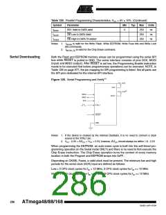
SPI Serial Programming
Characteristics
For characteristics of the SPI module see “SPI Timing Characteristics” on page 295.
289
2545D–AVR–07/04

 ATMEL [ ATMEL ]