ATmega48/88/168
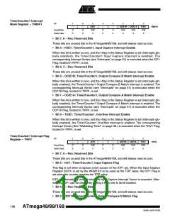
This flag is set in the timer clock cycle after the counter (TCNT1) value matches the Out-
put Compare Register B (OCR1B).
Note that a Forced Output Compare (FOC1B) strobe will not set the OCF1B Flag.
OCF1B is automatically cleared when the Output Compare Match B Interrupt Vector is
executed. Alternatively, OCF1B can be cleared by writing a logic one to its bit location.
• Bit 1 – OCF1A: Timer/Counter1, Output Compare A Match Flag
This flag is set in the timer clock cycle after the counter (TCNT1) value matches the Out-
put Compare Register A (OCR1A).
Note that a Forced Output Compare (FOC1A) strobe will not set the OCF1A Flag.
OCF1A is automatically cleared when the Output Compare Match A Interrupt Vector is
executed. Alternatively, OCF1A can be cleared by writing a logic one to its bit location.
• Bit 0 – TOV1: Timer/Counter1, Overflow Flag
The setting of this flag is dependent of the WGM13:0 bits setting. In Normal and CTC
modes, the TOV1 Flag is set when the timer overflows. Refer to Table 57 on page 127
for the TOV1 Flag behavior when using another WGM13:0 bit setting.
TOV1 is automatically cleared when the Timer/Counter1 Overflow Interrupt Vector is
executed. Alternatively, TOV1 can be cleared by writing a logic one to its bit location.
131
2545D–AVR–07/04

 ATMEL [ ATMEL ]