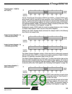
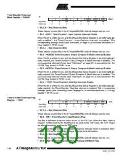
Timer/Counter1 Interrupt
Mask Register – TIMSK1
Bit
7
–
6
–
5
ICIE1
R/W
0
4
–
3
–
2
OCIE1B
R/W
0
1
OCIE1A
R/W
0
0
TOIE1
R/W
0
TIMSK1
Read/Write
Initial Value
R
0
R
0
R
0
R
0
• Bit 7, 6 – Res: Reserved Bits
These bits are unused bits in the ATmega48/88/168, and will always read as zero.
• Bit 5 – ICIE1: Timer/Counter1, Input Capture Interrupt Enable
When this bit is written to one, and the I-flag in the Status Register is set (interrupts glo-
bally enabled), the Timer/Counter1 Input Capture interrupt is enabled. The
corresponding Interrupt Vector (see “Interrupts” on page 51) is executed when the ICF1
Flag, located in TIFR1, is set.
• Bit 4, 3 – Res: Reserved Bits
These bits are unused bits in the ATmega48/88/168, and will always read as zero.
• Bit 2 – OCIE1B: Timer/Counter1, Output Compare B Match Interrupt Enable
When this bit is written to one, and the I-flag in the Status Register is set (interrupts glo-
bally enabled), the Timer/Counter1 Output Compare B Match interrupt is enabled. The
corresponding Interrupt Vector (see “Interrupts” on page 51) is executed when the
OCF1B Flag, located in TIFR1, is set.
• Bit 1 – OCIE1A: Timer/Counter1, Output Compare A Match Interrupt Enable
When this bit is written to one, and the I-flag in the Status Register is set (interrupts glo-
bally enabled), the Timer/Counter1 Output Compare A Match interrupt is enabled. The
corresponding Interrupt Vector (see “Interrupts” on page 51) is executed when the
OCF1A Flag, located in TIFR1, is set.
• Bit 0 – TOIE1: Timer/Counter1, Overflow Interrupt Enable
When this bit is written to one, and the I-flag in the Status Register is set (interrupts glo-
bally enabled), the Timer/Counter1 Overflow interrupt is enabled. The corresponding
Interrupt Vector (See “Watchdog Timer” on page 46.) is executed when the TOV1 Flag,
located in TIFR1, is set.
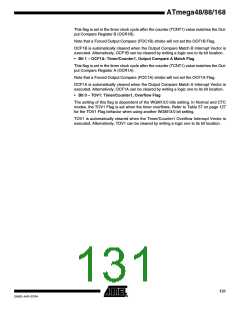
Timer/Counter1 Interrupt Flag
Register – TIFR1
Bit
7
–
6
–
5
4
–
3
–
2
OCF1B
R/W
0
1
OCF1A
R/W
0
0
TOV1
R/W
0
ICF1
R/W
0
TIFR1
Read/Write
Initial Value
R
0
R
0
R
0
R
0
• Bit 7, 6 – Res: Reserved Bits
These bits are unused bits in the ATmega48/88/168, and will always read as zero.
• Bit 5 – ICF1: Timer/Counter1, Input Capture Flag
This flag is set when a capture event occurs on the ICP1 pin. When the Input Capture
Register (ICR1) is set by the WGM13:0 to be used as the TOP value, the ICF1 Flag is
set when the counter reaches the TOP value.
ICF1 is automatically cleared when the Input Capture Interrupt Vector is executed. Alter-
natively, ICF1 can be cleared by writing a logic one to its bit location.
• Bit 4, 3 – Res: Reserved Bits
These bits are unused bits in the ATmega48/88/168, and will always read as zero.
• Bit 2 – OCF1B: Timer/Counter1, Output Compare B Match Flag
130
ATmega48/88/168
2545D–AVR–07/04

 ATMEL [ ATMEL ]