ATmega640/1280/1281/2560/2561
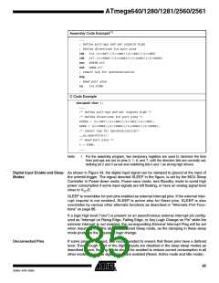
Assembly Code Example(1)
...
; Define pull-ups and set outputs high
; Define directions for port pins
ldi
ldi
out
out
r16,(1<<PB7)|(1<<PB6)|(1<<PB1)|(1<<PB0)
r17,(1<<DDB3)|(1<<DDB2)|(1<<DDB1)|(1<<DDB0)
PORTB,r16
DDRB,r17
; Insert nop for synchronization
nop
; Read port pins
in
r16,PINB
...
C Code Example
unsigned char i;
...
/* Define pull-ups and set outputs high */
/* Define directions for port pins */
PORTB = (1<<PB7)|(1<<PB6)|(1<<PB1)|(1<<PB0);
DDRB = (1<<DDB3)|(1<<DDB2)|(1<<DDB1)|(1<<DDB0);
/* Insert nop for synchronization*/
__no_operation();
/* Read port pins */
i = PINB;
...
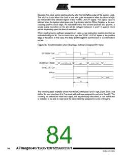
Note:
1. For the assembly program, two temporary registers are used to minimize the time
from pull-ups are set on pins 0, 1, 6, and 7, until the direction bits are correctly set,
defining bit 2 and 3 as low and redefining bits 0 and 1 as strong high drivers.
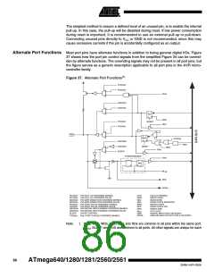
Digital Input Enable and Sleep As shown in Figure 34, the digital input signal can be clamped to ground at the input of
Modes
the schmitt-trigger. The signal denoted SLEEP in the figure, is set by the MCU Sleep
Controller in Power-down mode, Power-save mode, and Standby mode to avoid high
power consumption if some input signals are left floating, or have an analog signal level
close to VCC/2.
SLEEP is overridden for port pins enabled as external interrupt pins. If the external inter-
rupt request is not enabled, SLEEP is active also for these pins. SLEEP is also
overridden by various other alternate functions as described in “Alternate Port Func-
tions” on page 86.
If a logic high level (“one”) is present on an asynchronous external interrupt pin config-
ured as “Interrupt on Rising Edge, Falling Edge, or Any Logic Change on Pin” while the
external interrupt is not enabled, the corresponding External Interrupt Flag will be set
when resuming from the above mentioned Sleep mode, as the clamping in these sleep
mode produces the requested logic change.
Unconnected Pins
If some pins are unused, it is recommended to ensure that these pins have a defined
level. Even though most of the digital inputs are disabled in the deep sleep modes as
described above, floating inputs should be avoided to reduce current consumption in all
other modes where the digital inputs are enabled (Reset, Active mode and Idle mode).
85
2549A–AVR–03/05

 ATMEL [ ATMEL ]