ATmega640/1280/1281/2560/2561
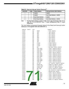
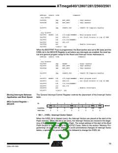
Address Labels Code
Comments
.org 0x0002
0x00002
0x00004
...
jmp
jmp
...
jmp
EXT_INT0
EXT_INT1
...
; IRQ0 Handler
; IRQ1 Handler
;
0x00070
;
USART3_TXC
; USART3 TX Complete Handler
.org 0x1F000
0x1F000 RESET: ldi
r16,high(RAMEND) ; Main program start
0x1F001
0x1F002
out
ldi
SPH,r16
; Set Stack Pointer to top of RAM
r16,low(RAMEND)
SPL,r16
0x1F003
0x1F004
out
sei
; Enable interrupts
0x1F005
<instr> xxx
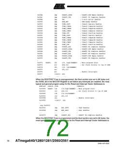
When the BOOTRST Fuse is programmed, the Boot section size set to 8K bytes and the
IVSEL bit in the MCUCR Register is set before any interrupts are enabled, the most typ-
ical and general program setup for the Reset and Interrupt Vector Addresses is:
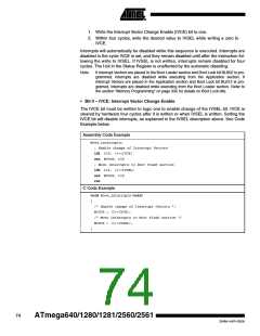
Address Labels Code
Comments
;
.org 0x1F000
0x1F000
0x1F002
jmp
jmp
RESET
EXT_INT0
; Reset handler
; IRQ0 Handler
0x1F004
...
jmp
...
jmp
EXT_INT1
...
; IRQ1 Handler
;
0x1F070
;
USART3_TXC
; USART3 TX Complete Handler
0x1F072 RESET: ldi
r16,high(RAMEND) ; Main program start
0x1F073
0x1F074
out
ldi
SPH,r16
; Set Stack Pointer to top of RAM
r16,low(RAMEND)
SPL,r16
0x1F075
0x1F076
out
sei
; Enable interrupts
0x1FO77
<instr> xxx
Moving Interrupts Between
Application and Boot Space
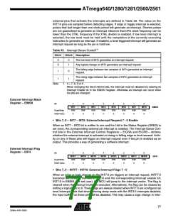
The General Interrupt Control Register controls the placement of the Interrupt Vector
table.
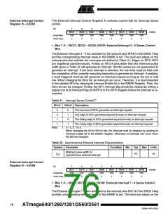
MCU Control Register –
MCUCR
Bit
7
6
–
5
–
4
3
–
2
–
1
IVSEL
R/W
0
0
IVCE
R/W
0
JTD
R/W
0
PUD
R/W
0
MCUCR
Read/Write
Initial Value
R
0
R
0
R
0
R
0
• Bit 1 – IVSEL: Interrupt Vector Select
When the IVSEL bit is cleared (zero), the Interrupt Vectors are placed at the start of the
Flash memory. When this bit is set (one), the Interrupt Vectors are moved to the begin-
ning of the Boot Loader section of the Flash. The actual address of the start of the Boot
Flash Section is determined by the BOOTSZ Fuses. Refer to the section “Memory Pro-
gramming” on page 335 for details. To avoid unintentional changes of Interrupt Vector
tables, a special write procedure must be followed to change the IVSEL bit:
73
2549A–AVR–03/05

 ATMEL [ ATMEL ]