0x004A
0x004C
0x004E
0x0050
0x0052
0x0054
0x0056
0x0058
0x005A
0x005C
0x005E
0x0060
0x0062
0x0064
0x0066
0x0068
0x006A
0x006C
0x006E
0x0070
;
jmp
jmp
jmp
jmp
jmp
jmp
jmp
jmp
jmp
jmp
jmp
jmp
jmp
jmp
jmp
jmp
jmp
jmp
jmp
jmp
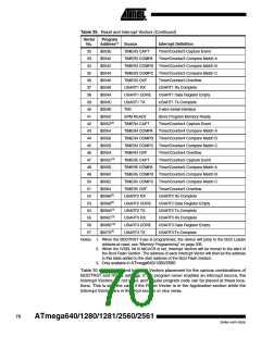
USART1_UDRE
USART1_TXC
TWI
; USART1,UDR Empty Handler
; USART1 TX Complete Handler
; 2-wire Serial Handler
SPM_RDY
; SPM Ready Handler
TIM4_CAPT
TIM4_COMPA
TIM4_COMPB
TIM4_COMPC
TIM4_OVF
; Timer4 Capture Handler
; Timer4 CompareA Handler
; Timer4 CompareB Handler
; Timer4 CompareC Handler
; Timer4 Overflow Handler
; Timer5 Capture Handler
; Timer5 CompareA Handler
; Timer5 CompareB Handler
; Timer5 CompareC Handler
; Timer5 Overflow Handler
; USART2 RX Complete Handler
; USART2,UDR Empty Handler
; USART2 TX Complete Handler
; USART3 RX Complete Handler
; USART3,UDR Empty Handler
; USART3 TX Complete Handler
TIM5_CAPT
TIM5_COMPA
TIM5_COMPB
TIM5_COMPC
TIM5_OVF
USART2_RXC
USART2_UDRE
USART2_TXC
USART3_RXC
USART3_UDRE
USART3_TXC
0x0072
0x0073
0x0074
0x0075
0x0076
0x0077
...
RESET:
ldi
out
ldi
out
sei
r16, high(RAMEND)
SPH,r16
; Main program start
; Set Stack Pointer to top of RAM
r16, low(RAMEND)
SPL,r16
; Enable interrupts
<instr> xxx
... ...
...
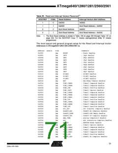
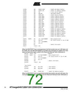
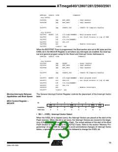
When the BOOTRST Fuse is unprogrammed, the Boot section size set to 8K bytes and
the IVSEL bit in the MCUCR Register is set before any interrupts are enabled, the most
typical and general program setup for the Reset and Interrupt Vector Addresses is:
Address Labels Code
Comments
0x00000 RESET: ldi
r16,high(RAMEND) ; Main program start
0x00001
0x00002
out
ldi
SPH,r16
; Set Stack Pointer to top of RAM
r16,low(RAMEND)
SPL,r16
0x00003
0x00004
out
sei
; Enable interrupts
0x00005
;
<instr> xxx
.org 0x1F002
0x1F002
0x1F004
...
jmp
jmp
...
jmp
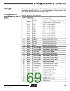
EXT_INT0
; IRQ0 Handler
EXT_INT1
...
; IRQ1 Handler
;
0x1FO70
USART3_TXC
; USART3 TX Complete Handler
When the BOOTRST Fuse is programmed and the Boot section size set to 8K bytes, the
most typical and general program setup for the Reset and Interrupt Vector Addresses is:
72
ATmega640/1280/1281/2560/2561
2549A–AVR–03/05

 ATMEL [ ATMEL ]