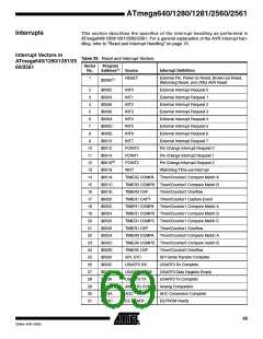
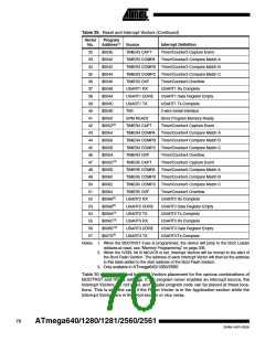
Table 29. Reset and Interrupt Vectors (Continued)
Vector
No.
Program
Address(2) Source
Interrupt Definition
32
33
34
35
36
37
38
39
40
41
42
43
44
45
46
47
48
49
50
51
52
53
54
55
56
57
$003E
$0040
TIMER3 CAPT
TIMER3 COMPA
Timer/Counter3 Capture Event
Timer/Counter3 Compare Match A
$0042
TIMER3 COMPB Timer/Counter3 Compare Match B
TIMER3 COMPC Timer/Counter3 Compare Match C
$0044
$0046
TIMER3 OVF
USART1 RX
USART1 UDRE
USART1 TX
TWI
Timer/Counter3 Overflow
USART1 Rx Complete
$0048
$004A
$004C
$004E
$0050
USART1 Data Register Empty
USART1 Tx Complete
2-wire Serial Interface
SPM READY
TIMER4 CAPT
TIMER4 COMPA
Store Program Memory Ready
Timer/Counter4 Capture Event
Timer/Counter4 Compare Match A
$0052(3)
$0054
$0056
TIMER4 COMPB Timer/Counter4 Compare Match B
TIMER4 COMPC Timer/Counter4 Compare Match C
$0058
$005A
$005C(3)
$005E
$0060
TIMER4 OVF
Timer/Counter4 Overflow
TIMER5 CAPT
TIMER5 COMPA
Timer/Counter5 Capture Event
Timer/Counter5 Compare Match A
TIMER5 COMPB Timer/Counter5 Compare Match B
TIMER5 COMPC Timer/Counter5 Compare Match C
$0062
$0064
TIMER5 OVF
USART2 RX
USART2 UDRE
USART2 TX
USART3 RX
USART3 UDRE
USART3 TX
Timer/Counter5 Overflow
USART2 Rx Complete
$0066(3)
$0068(3)
$006A(3)
$006C(3)
$006E(3))
$0070(3)
USART2 Data Register Empty
USART2 Tx Complete
USART3 Rx Complete
USART3 Data Register Empty
USART3 Tx Complete
Notes: 1. When the BOOTRST Fuse is programmed, the device will jump to the Boot Loader
address at reset, see “Memory Programming” on page 335.
2. When the IVSEL bit in MCUCR is set, Interrupt Vectors will be moved to the start of
the Boot Flash Section. The address of each Interrupt Vector will then be the address
in this table added to the start address of the Boot Flash Section.
3. Only available in ATmega640/1280/2560
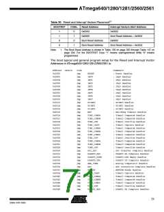
Table 30 shows reset and Interrupt Vectors placement for the various combinations of
BOOTRST and IVSEL settings. If the program never enables an interrupt source, the
Interrupt Vectors are not used, and regular program code can be placed at these loca-
tions. This is also the case if the Reset Vector is in the Application section while the
Interrupt Vectors are in the Boot section or vice versa.
70
ATmega640/1280/1281/2560/2561
2549A–AVR–03/05

 ATMEL [ ATMEL ]