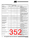
Table 163. Serial Programming Instruction Set
Instruction Format
Byte 2 Byte 3
Instruction
Byte 1
Byte4
Operation
Programming Enable
1010 1100 0101 0011 xxxx xxxx xxxx xxxx Enable Serial Programming after
RESET goes low.
Chip Erase
1010 1100 100x xxxx xxxx xxxx xxxx xxxx Chip Erase EEPROM and Flash.
Load Extended Address Byte 0100 1101 0000 0000 cccc cccc xxxx xxxx Defines Extended Address Byte for
Read Program Memory and Write
Program Memory Page.
Read Program Memory
0010 H000 aaaa aaaa bbbb bbbb oooo oooo Read H (high or low) data o from
Program memory at word address
c:a:b.
Load Program Memory Page
0100 H000 xxxx xxxx xxbb bbbb iiii iiii Write H (high or low) data i to Program
Memory page at word address b. Data
low byte must be loaded before Data
high byte is applied within the same
address.
Write Program Memory Page 0100 1100 aaaa aaaa bbxx xxxx xxxx xxxx Write Program Memory Page at
address c:a:b.
Read EEPROM Memory
1010 0000 0000 aaaa bbbb bbbb oooo oooo Read data o from EEPROM memory at
address a:b.
Write EEPROM Memory
1100 0000 0000 aaaa bbbb bbbb iiii iiii Write data i to EEPROM memory at
address a:b.
Load EEPROM Memory
Page (page access)
1100 0001 0000 0000 0000 00bb iiii iiii Load data i to EEPROM memory page
buffer. After data is loaded, program
EEPROM page.
Write EEPROM Memory
Page (page access)
1100 0010 0000 aaaa bbbb bb00 xxxx xxxx Write EEPROM page at address a:b.
Read Lock bits
0101 1000 0000 0000 xxxx xxxx xxoo oooo Read Lock bits. “0” = programmed, “1”
= unprogrammed. See Table 148 on
page 335 for details.
Write Lock bits
1010 1100 111x xxxx xxxx xxxx 11ii iiii Write Lock bits. Set bits = “0” to
program Lock bits. See Table 148 on
page 335 for details.
Read Signature Byte
Write Fuse bits
0011 0000 000x xxxx xxxx xxbb oooo oooo Read Signature Byte o at address b.
1010 1100 1010 0000 xxxx xxxx iiii iiii Set bits = “0” to program, “1” to
unprogram. See Table 124 on page
287 for details.
Write Fuse High bits
Write Extended Fuse Bits
Read Fuse bits
1010 1100 1010 1000 xxxx xxxx iiii iiii Set bits = “0” to program, “1” to
unprogram. See Table 123 on page
279 for details.
1010 1100 1010 0100 xxxx xxxx iiii iiii Set bits = “0” to program, “1” to
unprogram. See Table 150 on page
336 for details.
0101 0000 0000 0000 xxxx xxxx oooo oooo Read Fuse bits. “0” = programmed, “1”
= unprogrammed. See Table 124 on
page 287 for details.
352
ATmega640/1280/1281/2560/2561
2549A–AVR–03/05

 ATMEL [ ATMEL ]