ATmega640/1280/1281/2560/2561
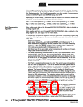
Flash memory, use the instruction Load Extended Address Byte to define the
upper address byte, which is not included in the Read Program Memory instruc-
tion. The extended address byte is stored until the command is re-issued, i.e.,
the command needs only be issued for the first page, and when crossing the
64KWord boundary.
7. At the end of the programming session, RESET can be set high to commence
normal operation.
8. Power-off sequence (if needed):
Set RESET to “1”.
Turn VCC power off.
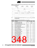
Table 162. Minimum Wait Delay Before Writing the Next Flash or EEPROM Location
Symbol
Minimum Wait Delay
4.5 ms
tWD_FLASH
tWD_EEPROM
tWD_ERASE
9.0 ms
9.0 ms
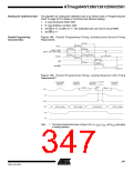
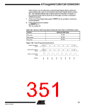
Figure 149. Serial Programming Waveforms
SERIAL DATA INPUT
(MOSI)
MSB
LSB
LSB
SERIAL DATA OUTPUT
(MISO)
MSB
SERIAL CLOCK INPUT
(SCK)
SAMPLE
351
2549A–AVR–03/05

 ATMEL [ ATMEL ]