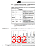
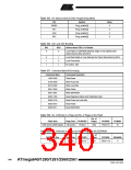
Table 149. Lock Bit Protection Modes(1)(2) (Continued)
Memory Lock Bits
Protection Type
BLB1 Mode BLB12 BLB11
No restrictions for SPM or (E)LPM accessing the Boot
Loader section.
1
2
1
1
1
0
SPM is not allowed to write to the Boot Loader section.
SPM is not allowed to write to the Boot Loader section,
and (E)LPM executing from the Application section is not
allowed to read from the Boot Loader section. If Interrupt
Vectors are placed in the Application section, interrupts
are disabled while executing from the Boot Loader section.
3
4
0
0
0
1
(E)LPM executing from the Application section is not
allowed to read from the Boot Loader section. If Interrupt
Vectors are placed in the Application section, interrupts
are disabled while executing from the Boot Loader section.
Notes: 1. Program the Fuse bits and Boot Lock bits before programming the LB1 and LB2.
2. “1” means unprogrammed, “0” means programmed
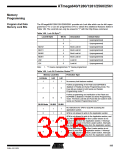
Fuse Bits
The ATmega640/1280/1281/2560/2561 has four Fuse bytes. Table 150 - Table 152
describe briefly the functionality of all the fuses and how they are mapped into the Fuse
bytes. Note that the fuses are read as logical zero, “0”, if they are programmed.
Table 150. Extended Fuse Byte
Fuse Low Byte
Bit No
Description
Default Value
–
–
–
–
–
7
–
1
6
5
4
3
2
1
0
–
1
–
1
–
1
–
1
BODLEVEL2(1)
BODLEVEL1(1)
BODLEVEL0(1)
Brown-out Detector trigger level
Brown-out Detector trigger level
Brown-out Detector trigger level
1 (unprogrammed)
1 (unprogrammed)
1 (unprogrammed)
Note:
1. See Table 24 on page 60 for BODLEVEL Fuse decoding.
336
ATmega640/1280/1281/2560/2561
2549A–AVR–03/05

 ATMEL [ ATMEL ]