Note:
1. For details about these two section, see “NRWW – No Read-While-Write Section” on
page 318 and “RWW – Read-While-Write Section” on page 318.
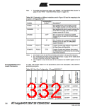
Table 144. Explanation of different variables used in Figure 138 and the mapping to the
Z-pointer, ATmega1280/1281
Corresponding
Variable
Z-value(2)
Description(1)
PCMSB
15
6
Most significant bit in the Program Counter.
(The Program Counter is 16 bits PC[15:0])
PAGEMSB
ZPCMSB
Most significant bit which is used to address the
words within one page (128 words in a page
requires seven bits PC [6:0]).
Z16(3)
Z7
Bit in Z-pointer that is mapped to PCMSB.
Because Z0 is not used, the ZPCMSB equals
PCMSB + 1.
ZPAGEMSB
Bit in Z-pointer that is mapped to PCMSB.
Because Z0 is not used, the ZPAGEMSB
equals PAGEMSB + 1.
PCPAGE
PC[15:7]
PC[6:0]
Z16(3):Z8
Z7:Z1
Program Counter page address: Page select,
for Page Erase and Page Write
PCWORD
Program Counter word address: Word select,
for filling temporary buffer (must be zero during
Page Write operation)
Notes: 1. Z0: should be zero for all SPM commands, byte select for the (E)LPM instruction.
2. See “Addressing the Flash During Self-Programming” on page 322 for details about
the use of Z-pointer during Self-Programming.
3. The Z-register is only 16 bits wide. Bit 16 is located in the RAMPZ register in the I/O
map.
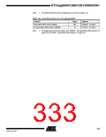
ATmega2560/2561 Boot
Loader Parameters
In Table 145 through Table 147, the parameters used in the description of the Self-Pro-
gramming are given.
Table 145. Boot Size Configuration, ATmega2560/2561(1)
512
words
0x00000 -
0x1FDFF
0x1FE00 -
0x1FFFF
1
1
0
0
1
0
1
0
4
8
0x1FDFF
0x1FBFF
0x1F7FF
0x1EFFF
0x1FE00
0x1FC00
0x1F800
0x1F000
1024
words
0x00000 -
0x1FBFF
0x1FC00 -
0x1FFFF
2048
words
0x00000 -
0x1F7FF
0x1F800 -
0x1FFFF
16
32
4096
words
0x00000 -
0x1EFFF
0x1F000 -
0x1FFFF
332
ATmega640/1280/1281/2560/2561
2549A–AVR–03/05

 ATMEL [ ATMEL ]