ATmega640/1280/1281/2560/2561
USART
The Universal Synchronous and Asynchronous serial Receiver and Transmitter
(USART) is a highly flexible serial communication device. The main features are:
• Full Duplex Operation (Independent Serial Receive and Transmit Registers)
• Asynchronous or Synchronous Operation
• Master or Slave Clocked Synchronous Operation
• High Resolution Baud Rate Generator
• Supports Serial Frames with 5, 6, 7, 8, or 9 Data Bits and 1 or 2 Stop Bits
• Odd or Even Parity Generation and Parity Check Supported by Hardware
• Data OverRun Detection
• Framing Error Detection
• Noise Filtering Includes False Start Bit Detection and Digital Low Pass Filter
• Three Separate Interrupts on TX Complete, TX Data Register Empty and RX Complete
• Multi-processor Communication Mode
• Double Speed Asynchronous Communication Mode
Quad USART
The ATmega640/1280/1281/2560/2561 has four USART’s, USART0, USART1,
USART2, and USART3. The functionality for all four USART’s is described below.
USART0, USART1, USART2, and USART3 have different I/O registers as shown in
“Register Summary” on page 385.
Overview
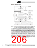
A simplified block diagram of the USART Transmitter is shown in Figure 83 on page
206. CPU accessible I/O Registers and I/O pins are shown in bold.
The Power Reducion USART0 bit, PRUSART0, in “Power Reduction Register 0 -
PRR0” on page 54 must be disabled by writing a logical zero to it.
The Power Reducion USART1 bit, PRUSART1, in “Power Reduction Register 1 -
PRR1” on page 55 must be disabled by writing a logical zero to it.
The Power Reducion USART2 bit, PRUSART2, in “Power Reduction Register 1 -
PRR1” on page 55 must be disabled by writing a logical zero to it.
The Power Reducion USART3 bit, PRUSART3, in “Power Reduction Register 1 -
PRR1” on page 55 must be disabled by writing a logical zero to it.
205
2549A–AVR–03/05

 ATMEL [ ATMEL ]