ATmega640/1280/1281/2560/2561
• Bit 3 – OCIEnC: Timer/Countern, Output Compare C Match Interrupt Enable
When this bit is written to one, and the I-flag in the Status Register is set (interrupts glo-
bally enabled), the Timer/Countern Output Compare C Match interrupt is enabled. The
corresponding Interrupt Vector (See “Interrupts” on page 69.) is executed when the
OCFnC Flag, located in TIFRn, is set.
• Bit 2 – OCIEnB: Timer/Countern, Output Compare B Match Interrupt Enable
When this bit is written to one, and the I-flag in the Status Register is set (interrupts glo-
bally enabled), the Timer/Countern Output Compare B Match interrupt is enabled. The
corresponding Interrupt Vector (See “Interrupts” on page 69.) is executed when the
OCFnB Flag, located in TIFRn, is set.
• Bit 1 – OCIEnA: Timer/Countern, Output Compare A Match Interrupt Enable
When this bit is written to one, and the I-flag in the Status Register is set (interrupts glo-
bally enabled), the Timer/Countern Output Compare A Match interrupt is enabled. The
corresponding Interrupt Vector (See “Interrupts” on page 69.) is executed when the
OCFnA Flag, located in TIFRn, is set.
• Bit 0 – TOIEn: Timer/Countern, Overflow Interrupt Enable
When this bit is written to one, and the I-flag in the Status Register is set (interrupts glo-
bally enabled), the Timer/Countern Overflow interrupt is enabled. The corresponding
Interrupt Vector (See “Interrupts” on page 69.) is executed when the TOVn Flag, located
in TIFRn, is set.
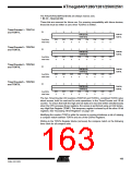
Timer/Counter1 Interrupt Flag
Register – TIFR1
Bit
7
–
6
–
5
4
–
3
OCF1C
R/W
0
2
OCF1B
R/W
0
1
OCF1A
R/W
0
0
TOV1
R/W
0
ICF1
R/W
0
TIFR1
TIFR3
TIFR4
TIFR5
Read/Write
Initial Value
R
0
R
0
R
0
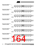
Timer/Counter3 Interrupt Flag
Register – TIFR3
Bit
7
–
6
–
5
4
–
3
OCF3C
R/W
0
2
OCF3B
R/W
0
1
OCF3A
R/W
0
0
TOV3
R/W
0
ICF3
R/W
0
Read/Write
Initial Value
R
0
R
0
R
0
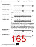
Timer/Counter4 Interrupt Flag
Register – TIFR4
Bit
7
–
6
–
5
4
–
3
OCF4C
R/W
0
2
OCF4B
R/W
0
1
OCF4A
R/W
0
0
TOV4
R/W
0
ICF4
R/W
0
Read/Write
Initial Value
R
0
R
0
R
0
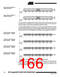
Timer/Counter5 Interrupt Flag
Register – TIFR5
Bit
7
–
6
–
5
4
–
3
OCF5C
R/W
0
2
OCF5B
R/W
0
1
OCF5A
R/W
0
0
TOV5
R/W
0
ICF5
R/W
0
Read/Write
Initial Value
R
0
R
0
R
0
• Bit 5 – ICFn: Timer/Countern, Input Capture Flag
This flag is set when a capture event occurs on the ICPn pin. When the Input Capture
Register (ICRn) is set by the WGMn3:0 to be used as the TOP value, the ICFn Flag is
set when the counter reaches the TOP value.
167
2549A–AVR–03/05

 ATMEL [ ATMEL ]