ATmega16(L)
• SDA – Port C, Bit 1
SDA, Two-wire Serial Interface Data: When the TWEN bit in TWCR is set (one) to
enable the Two-wire Serial Interface, pin PC1 is disconnected from the port and
becomes the Serial Data I/O pin for the Two-wire Serial Interface. In this mode, there is
a spike filter on the pin to suppress spikes shorter than 50 ns on the input signal, and the
pin is driven by an open drain driver with slew-rate limitation. When this pin is used by
the Two-wire Serial Interface, the pull-up can still be controlled by the PORTC1 bit.
• SCL – Port C, Bit 0
SCL, Two-wire Serial Interface Clock: When the TWEN bit in TWCR is set (one) to
enable the Two-wire Serial Interface, pin PC0 is disconnected from the port and
becomes the Serial Clock I/O pin for the Two-wire Serial Interface. In this mode, there is
a spike filter on the pin to suppress spikes shorter than 50 ns on the input signal, and the
pin is driven by an open drain driver with slew-rate limitation. When this pin is used by
the Two-wire Serial Interface, the pull-up can still be controlled by the PORTC0 bit.
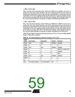
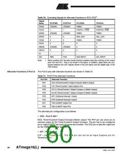
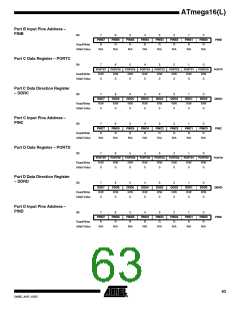
Table 29 and Table 30 relate the alternate functions of Port C to the overriding signals
shown in Figure 26 on page 52.
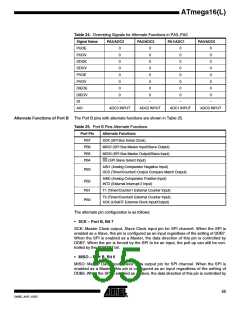
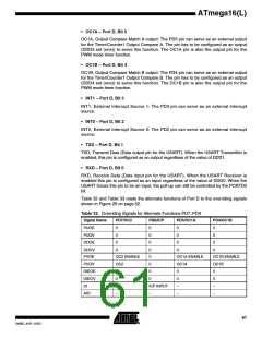
Table 29. Overriding Signals for Alternate Functions in PC7..PC4
Signal
Name
PUOE
PUOV
DDOE
DDOV
PVOE
PVOV
DIEOE
DIEOV
DI
PC7/TOSC2
PC6/TOSC1
PC5/TDI
PC4/TDO
AS2
AS2
JTAGEN
JTAGEN
0
0
1
0
AS2
AS2
JTAGEN
JTAGEN
0
0
0
SHIFT_IR + SHIFT_DR
0
0
0
JTAGEN
0
0
0
TDO
AS2
AS2
JTAGEN
JTAGEN
0
0
0
0
–
–
–
–
–
AIO
T/C2 OSC OUTPUT
T/C2 OSC INPUT
TDI
59
2466E–AVR–10/02

 ATMEL [ ATMEL ]