Low-frequency Crystal
Oscillator
To use a 32.768 kHz watch crystal as the clock source for the device, the Low-fre-
quency Crystal Oscillator must be selected by setting the CKSEL fuses to “1001”. The
crystal should be connected as shown in Figure 12. By programming the CKOPT Fuse,
the user can enable internal capacitors on XTAL1 and XTAL2, thereby removing the
need for external capacitors. The internal capacitors have a nominal value of 36 pF.
Refer to the 32 kHz Crystal Oscillator application note for details on Oscillator operation
and how to choose appropriate values for C1 and C2.
When this Oscillator is selected, start-up times are determined by the SUT fuses as
shown in Table 6.
Table 6. Start-up Times for the Low-frequency Crystal Oscillator Clock Selection
Start-up Time from
Power-down and
Power-save
Additional Delay
from Reset
SUT1..0
00
(VCC = 5.0V)
Recommended Usage
1K CK(1)
1K CK(1)
32K CK
4.1 ms
65 ms
65 ms
Fast rising power or BOD enabled
Slowly rising power
01
10
Stable frequency at start-up
11
Reserved
Note:
1. These options should only be used if frequency stability at start-up is not important for
the application.
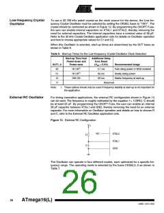
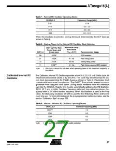
External RC Oscillator
For timing insensitive applications, the external RC configuration shown in Figure 13
can be used. The frequency is roughly estimated by the equation f = 1/(3RC). C should
be at least 22 pF. By programming the CKOPT Fuse, the user can enable an internal
36 pF capacitor between XTAL1 and GND, thereby removing the need for an external
capacitor. For more information on Oscillator operation and details on how to choose R
and C, refer to the External RC Oscillator application note.
Figure 13. External RC Configuration
VCC
NC
XTAL2
XTAL1
GND
R
C
The Oscillator can operate in four different modes, each optimized for a specific fre-
quency range. The operating mode is selected by the fuses CKSEL3..0 as shown in
Table 7.
26
ATmega16(L)
2466E–AVR–10/02

 ATMEL [ ATMEL ]