System Clock and
Clock Options
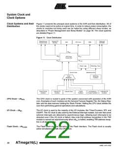
Clock Systems and their Figure 11 presents the principal clock systems in the AVR and their distribution. All of
the clocks need not be active at a given time. In order to reduce power consumption, the
Distribution
clocks to modules not being used can be halted by using different sleep modes, as
described in “Power Management and Sleep Modes” on page 30. The clock systems
are detailed Figure 11.
Figure 11. Clock Distribution
Asynchronous
Timer/Counter
General I/O
Modules
Flash and
EEPROM
ADC
CPU Core
RAM
clkADC
clkI/O
clkCPU
AVR Clock
Control Unit
clkASY
clkFLASH
Reset Logic
Watchdog Timer
Source Clock
Watchdog Clock
Clock
Multiplexer
Watchdog
Oscillator
Timer/Counter
Oscillator
External RC
Oscillator
Crystal
Oscillator
Low-frequency
Crystal Oscillator
Calibrated RC
Oscillator
External Clock
CPU Clock – clkCPU
I/O Clock – clkI/O
The CPU clock is routed to parts of the system concerned with operation of the AVR
core. Examples of such modules are the General Purpose Register File, the Status Reg-
ister and the data memory holding the Stack Pointer. Halting the CPU clock inhibits the
core from performing general operations and calculations.
The I/O clock is used by the majority of the I/O modules, like Timer/Counters, SPI, and
USART. The I/O clock is also used by the External Interrupt module, but note that some
external interrupts are detected by asynchronous logic, allowing such interrupts to be
detected even if the I/O clock is halted. Also note that address recognition in the TWI
module is carried out asynchronously when clkI/O is halted, enabling TWI address recep-
tion in all sleep modes.
Flash Clock – clkFLASH
The Flash clock controls operation of the Flash interface. The Flash clock is usually
active simultaneously with the CPU clock.
22
ATmega16(L)
2466E–AVR–10/02

 ATMEL [ ATMEL ]