ATmega16(L)
Table 7. External RC Oscillator Operating Modes
CKSEL3..0
0101
Frequency Range (MHz)
≤ 0.9
0110
0.9 - 3.0
3.0 - 8.0
8.0 - 12.0
0111
1000
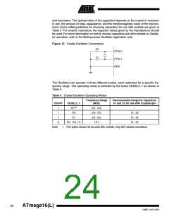
When this Oscillator is selected, start-up times are determined by the SUT fuses as
shown in Table 8.
Table 8. Start-up Times for the External RC Oscillator Clock Selection
Additional Delay
from Reset
Start-up Time from
Power-down and
Power-save
SUT1..0
00
(VCC = 5.0V)
Recommended Usage
BOD enabled
18 CK
18 CK
18 CK
6 CK(1)
–
01
4.1 ms
65 ms
4.1 ms
Fast rising power
10
Slowly rising power
11
Fast rising power or BOD enabled
Note:
1. This option should not be used when operating close to the maximum frequency of
the device.
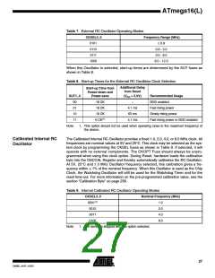
Calibrated Internal RC
Oscillator
The Calibrated Internal RC Oscillator provides a fixed 1.0, 2.0, 4.0, or 8.0 MHz clock. All
frequencies are nominal values at 5V and 25°C. This clock may be selected as the sys-
tem clock by programming the CKSEL fuses as shown in Table 9. If selected, it will
operate with no external components. The CKOPT Fuse should always be unpro-
grammed when using this clock option. During Reset, hardware loads the calibration
byte into the OSCCAL Register and thereby automatically calibrates the RC Oscillator.
At 5V, 25°C and 1.0 MHz Oscillator frequency selected, this calibration gives a fre-
quency within 1% of the nominal frequency. When this Oscillator is used as the Chip
Clock, the Watchdog Oscillator will still be used for the Watchdog Timer and for the
reset time-out. For more information on the pre-programmed calibration value, see the
section “Calibration Byte” on page 256.
Table 9. Internal Calibrated RC Oscillator Operating Modes
CKSEL3..0
0001(1)
0010
Nominal Frequency (MHz)
1.0
2.0
4.0
8.0
0011
0100
Note:
1. The device is shipped with this option selected.
27
2466E–AVR–10/02

 ATMEL [ ATMEL ]