ATmega16(L)
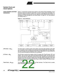
Asynchronous Timer Clock – The Asynchronous Timer clock allows the Asynchronous Timer/Counter to be clocked
clkASY
directly from an external 32 kHz clock crystal. The dedicated clock domain allows using
this Timer/Counter as a real-time counter even when the device is in sleep mode.
ADC Clock – clkADC
The ADC is provided with a dedicated clock domain. This allows halting the CPU and
I/O clocks in order to reduce noise generated by digital circuitry. This gives more accu-
rate ADC conversion results.
Clock Sources
The device has the following clock source options, selectable by Flash Fuse bits as
shown below. The clock from the selected source is input to the AVR clock generator,
and routed to the appropriate modules.
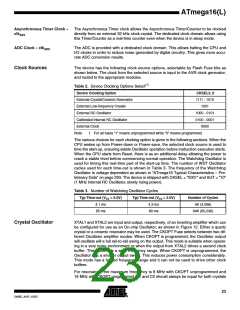
Table 2. Device Clocking Options Select(1)
Device Clocking Option
External Crystal/Ceramic Resonator
External Low-frequency Crystal
External RC Oscillator
CKSEL3..0
1111 - 1010
1001
1000 - 0101
0100 - 0001
0000
Calibrated Internal RC Oscillator
External Clock
Note:
1. For all fuses “1” means unprogrammed while “0” means programmed.
The various choices for each clocking option is given in the following sections. When the
CPU wakes up from Power-down or Power-save, the selected clock source is used to
time the start-up, ensuring stable Oscillator operation before instruction execution starts.
When the CPU starts from Reset, there is as an additional delay allowing the power to
reach a stable level before commencing normal operation. The Watchdog Oscillator is
used for timing this real-time part of the start-up time. The number of WDT Oscillator
cycles used for each time-out is shown in Table 3. The frequency of the Watchdog
Oscillator is voltage dependent as shown in “ATmega16 Typical Characteristics – Pre-
liminary Data” on page 293. The device is shipped with CKSEL = “0001” and SUT = “10”
(1 MHz Internal RC Oscillator, slowly rising power).
Table 3. Number of Watchdog Oscillator Cycles
Typ Time-out (VCC = 5.0V)
Typ Time-out (VCC = 3.0V)
Number of Cycles
4K (4,096)
4.1 ms
65 ms
4.3 ms
69 ms
64K (65,536)
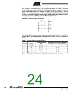
Crystal Oscillator
XTAL1 and XTAL2 are input and output, respectively, of an inverting amplifier which can
be configured for use as an On-chip Oscillator, as shown in Figure 12. Either a quartz
crystal or a ceramic resonator may be used. The CKOPT Fuse selects between two dif-
ferent Oscillator amplifier modes. When CKOPT is programmed, the Oscillator output
will oscillate will a full rail-to-rail swing on the output. This mode is suitable when operat-
ing in a very noisy environment or when the output from XTAL2 drives a second clock
buffer. This mode has a wide frequency range. When CKOPT is unprogrammed, the
Oscillator has a smaller output swing. This reduces power consumption considerably.
This mode has a limited frequency range and it can not be used to drive other clock
buffers.
For resonators, the maximum frequency is 8 MHz with CKOPT unprogrammed and
16 MHz with CKOPT programmed. C1 and C2 should always be equal for both crystals
23
2466E–AVR–10/02

 ATMEL [ ATMEL ]