and resonators. The optimal value of the capacitors depends on the crystal or resonator
in use, the amount of stray capacitance, and the electromagnetic noise of the environ-
ment. Some initial guidelines for choosing capacitors for use with crystals are given in
Table 4. For ceramic resonators, the capacitor values given by the manufacturer should
be used. For more information on how to choose capacitors and other details on Oscilla-
tor operation, refer to the Multi-purpose Oscillator application note.
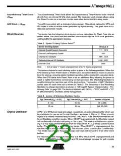
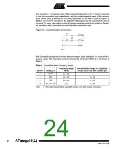
Figure 12. Crystal Oscillator Connections
C2
XTAL2
C1
XTAL1
GND
The Oscillator can operate in three different modes, each optimized for a specific fre-
quency range. The operating mode is selected by the fuses CKSEL3..1 as shown in
Table 4.
Table 4. Crystal Oscillator Operating Modes
Frequency Range
(MHz)
Recommended Range for Capacitors
C1 and C2 for Use with Crystals (pF)
CKOPT
CKSEL3..1
101(1)
1
1
1
0
0.4 - 0.9
0.9 - 3.0
3.0 - 8.0
1.0 ≤
–
110
12 - 22
12 - 22
12 - 22
111
101, 110, 111
Note:
1. This option should not be used with crystals, only with ceramic resonators.
24
ATmega16(L)
2466E–AVR–10/02

 ATMEL [ ATMEL ]