ATmega8U2/16U2/32U2
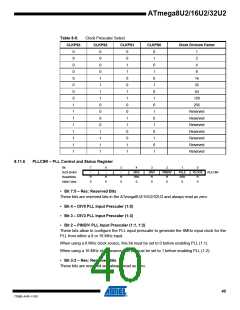
Table 8-9.
Clock Prescaler Select
CLKPS3
CLKPS2
CLKPS1
CLKPS0
Clock Division Factor
0
0
0
0
0
0
0
0
1
1
1
1
1
1
1
1
0
0
0
0
1
1
1
1
0
0
0
0
1
1
1
1
0
0
1
1
0
0
1
1
0
0
1
1
0
0
1
1
0
1
0
1
0
1
0
1
0
1
0
1
0
1
0
1
1
2
4
8
16
32
64
128
256
Reserved
Reserved
Reserved
Reserved
Reserved
Reserved
Reserved
8.11.6
PLLCSR – PLL Control and Status Register
Bit
7
–
6
–
5
–
4
DIV5
R/W
0
3
DIV3
R
2
1
PLLE
R/W
0
0
0x29 (0x49)
Read/Write
Initial Value
PINDIV
PLOCK
PLLCSR
R
0
R
0
R
0
R
0
R
0
0
• Bit 7:5 – Res: Reserved Bits
These bits are reserved bits in the ATmega8U2/16U2/32U2 and always read as zero.
• Bit 4 – DIV5 PLL Input Prescaler (1:5)
• Bit 3 – DIV3 PLL Input Prescaler (1:3)
• Bit 2 – PINDIV PLL Input Prescaler (1:1, 1:2)
These bits allow to configure the PLL input prescaler to generate the 8MHz input clock for the
PLL from either a 8 or 16 MHz input.
When using a 8 MHz clock source, this bit must be set to 0 before enabling PLL (1:1).
When using a 16 MHz clock source, this bit must be set to 1 before enabling PLL (1:2).
• Bit 3:2 – Res: Reserved Bits
These bits are reserved and always read as zero.
40
7799D–AVR–11/10

 ATMEL [ ATMEL ]