ATmega8U2/16U2/32U2
Watchdog, and the interrupt system to continue operating. This sleep mode basically halts clk-
CPU and clkFLASH, while allowing the other clocks to run.
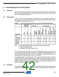
Idle mode enables the MCU to wake up from external triggered interrupts as well as internal
ones like the Timer Overflow, USART Transmit Complete or some USB interrupts (like SOFI,
WAKEUPI...). If wake-up from the Analog Comparator interrupt is not required, the Analog Com-
parator can be powered down by setting the ACD bit in the Analog Comparator Control and
Status Register – ACSR. This will reduce power consumption in Idle mode.
9.4
Power-down Mode
When the SM2:0 bits are written to 010, the SLEEP instruction makes the MCU enter Power-
down mode. In this mode, the external Oscillator is stopped, while the external interrupts, the 2-
wire Serial Interface, and the Watchdog continue operating (if enabled). Only an External Reset,
a Watchdog Reset, a Brown-out Reset, 2-wire Serial Interface address match, an external level
interrupt on INT7:4, an external interrupt on INT3:0, a pin change interrupt or an asynchronous
USB interrupt source (WAKEUPI only), can wake up the MCU. This sleep mode basically halts
all generated clocks, allowing operation of asynchronous modules only.
Note that if a level triggered interrupt is used for wake-up from Power-down mode, the changed
level must be held for some time to wake up the MCU. Refer to “External Interrupts” on page 84
for details.
When waking up from Power-down mode, there is a delay from the wake-up condition occurs
until the wake-up becomes effective. This allows the clock to restart and become stable after
having been stopped. The wake-up period is defined by the same CKSEL Fuses that define the
Reset Time-out period, as described in “Clock Sources” on page 29.
9.5
9.6
Power-save Mode
When the SM2:0 bits are written to 011, the SLEEP instruction makes the MCU enter Power-
save mode. This mode is identical to Power-down. This mode has been conserved for compati-
bility purpose with higher-end products.
Standby Mode
When the SM2:0 bits are 110 and an external crystal/resonator clock option is selected, the
SLEEP instruction makes the MCU enter Standby mode. This mode is identical to Power-down
with the exception that the Oscillator is kept running. From Standby mode, the device wakes up
in six clock cycles.
9.7
9.8
Extended Standby Mode
When the SM2:0 bits are 111 and an external crystal/resonator clock option is selected, the
SLEEP instruction makes the MCU enter Extended Standby mode. This mode is identical to
Power-save mode with the exception that the Oscillator is kept running. So Extended Standby
Mode is equivalent to Standy Mode, but is also conserved for compatibility purpose. From
Extended Standby mode, the device wakes up in six clock cycle.
Power Reduction Register
The Power Reduction Registers (PRR0 and PRR1), provides a method to stop the clock to indi-
vidual peripherals to reduce power consumption. See “PRR0 – Power Reduction Register 0” and
“PRR1 – Power Reduction Register 1” on page 46 for details. The current state of the peripheral
is frozen and the I/O registers can not be read or written. Resources used by the peripheral
43
7799D–AVR–11/10

 ATMEL [ ATMEL ]