ATmega169P
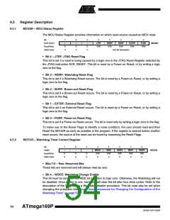
• Bit 3 – WDE: Watchdog Enable
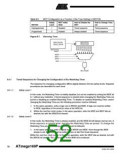
When the WDE is written to logic one, the Watchdog Timer is enabled, and if the WDE is written
to logic zero, the Watchdog Timer function is disabled. WDE can only be cleared if the WDCE bit
has logic level one. To disable an enabled Watchdog Timer, the following procedure must be
followed:
1. In the same operation, write a logic one to WDCE and WDE. A logic one must be written
to WDE even though it is set to one before the disable operation starts.
2. Within the next four clock cycles, write a logic 0 to WDE. This disables the Watchdog.
In safety level 2, it is not possible to disable the Watchdog Timer, even with the algorithm
described above. See ”Timed Sequences for Changing the Configuration of the Watchdog
Timer” on page 52.
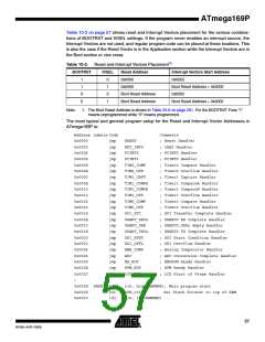
• Bits 2:0 – WDP2, WDP1, WDP0: Watchdog Timer Prescaler 2, 1, and 0
The WDP2, WDP1, and WDP0 bits determine the Watchdog Timer prescaling when the Watch-
dog Timer is enabled. The different prescaling values and their corresponding Timeout Periods
are shown in Table 9-6.
Table 9-6.
Watchdog Timer Prescale Select
Number of WDT
Oscillator Cycles
Typical Time-out at
VCC = 3.0V
Typical Time-out at
VCC = 5.0V
WDP2
WDP1
WDP0
0
0
0
0
1
1
1
1
0
0
1
1
0
0
1
1
0
1
0
1
0
1
0
1
16K cycles
15.4 ms
30.8 ms
61.6 ms
0.12 s
0.25 s
0.49 s
1.0 s
14.7 ms
29.3 ms
58.7 ms
0.12 s
0.23 s
0.47 s
0.9 s
32K cycles
64K cycles
128K cycles
256K cycles
512K cycles
1,024K cycles
2,048K cycles
2.0 s
1.9 s
Note:
Also see Figure 28-54 on page 363.
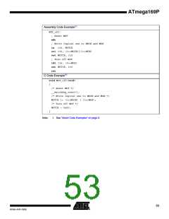
The following code example shows one assembly and one C function for turning off the WDT.
The example assumes that interrupts are controlled (e.g. by disabling interrupts globally) so that
no interrupts will occur during execution of these functions.
55
8018A–AVR–03/06

 ATMEL [ ATMEL ]