ATmega169P
9.3
Internal Voltage Reference
ATmega169P features an internal bandgap reference. This reference is used for Brown-out
Detection, and it can be used as an input to the Analog Comparator or the ADC.
9.3.1
Voltage Reference Enable Signals and Start-up Time
The voltage reference has a start-up time that may influence the way it should be used. The
start-up time is given in Table 9-4. To save power, the reference is not always turned on. The
reference is on during the following situations:
1. When the BOD is enabled (by programming the BODLEVEL [2..0] Fuse).
2. When the bandgap reference is connected to the Analog Comparator (by setting the
ACBG bit in ACSR).
3. When the ADC is enabled.
Thus, when the BOD is not enabled, after setting the ACBG bit or enabling the ADC, the user
must always allow the reference to start up before the output from the Analog Comparator or
ADC is used. To reduce power consumption in Power-down mode, the user can avoid the three
conditions above to ensure that the reference is turned off before entering Power-down mode.
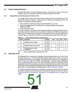
Table 9-4.
Symbol
Internal Voltage Reference Characteristics(1)
Parameter
Condition
Min
Typ
Max
Units
V
CC = 2.7V,
VBG
tBG
IBG
Bandgap reference voltage
1.0
1.1
1.2
V
TA = 25°C
VCC = 2.7V,
TA = 25°C
Bandgap reference start-up time
40
15
70
µs
Bandgap reference current
consumption
VCC = 2.7V,
TA = 25°C
µA
Note:
1. Values are guidelines only. Actual values are TBD.
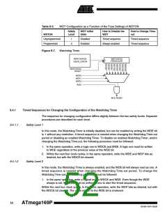
9.4
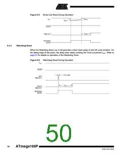
Watchdog Timer
The Watchdog Timer is clocked from a separate On-chip Oscillator which runs at 1 MHz. This is
the typical value at VCC = 5V. See characterization data for typical values at other VCC levels. By
controlling the Watchdog Timer prescaler, the Watchdog Reset interval can be adjusted as
shown in Table 9-6 on page 55. The WDR – Watchdog Reset – instruction resets the Watchdog
Timer. The Watchdog Timer is also reset when it is disabled and when a Chip Reset occurs.
Eight different clock cycle periods can be selected to determine the reset period. If the reset
period expires without another Watchdog Reset, the ATmega169P resets and executes from the
Reset Vector. For timing details on the Watchdog Reset, refer to Table 9-6 on page 55.
To prevent unintentional disabling of the Watchdog or unintentional change of time-out period,
two different safety levels are selected by the fuse WDTON as shown in Table 9-5. Refer to
”Timed Sequences for Changing the Configuration of the Watchdog Timer” on page 52 for
details.
51
8018A–AVR–03/06

 ATMEL [ ATMEL ]