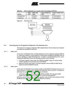
Table 9-5.
WDT Configuration as a Function of the Fuse Settings of WDTON
Safety
Level
WDT Initial
State
How to Disable the
WDT
How to Change Time-
out
WDTON
Unprogrammed
Programmed
1
2
Disabled
Enabled
Timed sequence
Always enabled
Timed sequence
Timed sequence
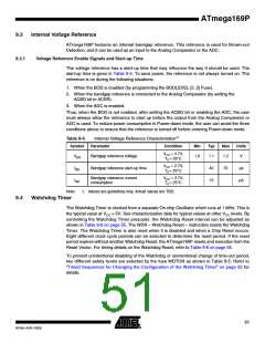
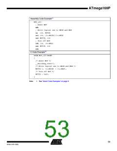
Figure 9-7. Watchdog Timer
WATCHDOG
OSCILLATOR
9.4.1
Timed Sequences for Changing the Configuration of the Watchdog Timer
The sequence for changing configuration differs slightly between the two safety levels. Separate
procedures are described for each level.
9.4.1.1
Safety Level 1
In this mode, the Watchdog Timer is initially disabled, but can be enabled by writing the WDE bit
to 1 without any restriction. A timed sequence is needed when changing the Watchdog Time-out
period or disabling an enabled Watchdog Timer. To disable an enabled Watchdog Timer, and/or
changing the Watchdog Time-out, the following procedure must be followed:
1. In the same operation, write a logic one to WDCE and WDE. A logic one must be written
to WDE regardless of the previous value of the WDE bit.
2. Within the next four clock cycles, in the same operation, write the WDE and WDP bits as
desired, but with the WDCE bit cleared.
9.4.1.2
Safety Level 2
In this mode, the Watchdog Timer is always enabled, and the WDE bit will always read as one. A
timed sequence is needed when changing the Watchdog Time-out period. To change the
Watchdog Time-out, the following procedure must be followed:
1. In the same operation, write a logical one to WDCE and WDE. Even though the WDE
always is set, the WDE must be written to one to start the timed sequence.
Within the next four clock cycles, in the same operation, write the WDP bits as desired, but with
the WDCE bit cleared. The value written to the WDE bit is irrelevant.
52
ATmega169P
8018A–AVR–03/06

 ATMEL [ ATMEL ]