ATmega169P
;
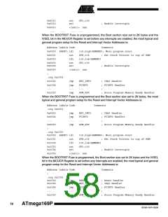
0x1C2E RESET: ldi
r16,high(RAMEND); Main program start
0x1C2F
0x1C30
out
ldi
SPH,r16
; Set Stack Pointer to top of RAM
r16,low(RAMEND)
SPL,r16
0x1C31
0x1C32
out
sei
; Enable interrupts
0x1C33
<instr> xxx
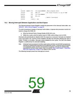
10.2 Moving Interrupts Between Application and Boot Space
The General Interrupt Control Register controls the placement of the Interrupt Vector table, see
”MCUCR – MCU Control Register” on page 60.
To avoid unintentional changes of Interrupt Vector tables, a special write procedure must be fol-
lowed to change the IVSEL bit:
a. Write the Interrupt Vector Change Enable (IVCE) bit to one.
b. Within four cycles, write the desired value to IVSEL while writing a zero to IVCE.
Interrupts will automatically be disabled while this sequence is executed. Interrupts are disabled
in the cycle IVCE is set, and they remain disabled until after the instruction following the write to
IVSEL. If IVSEL is not written, interrupts remain disabled for four cycles. The I-bit in the Status
Register is unaffected by the automatic disabling.
Note:
If Interrupt Vectors are placed in the Boot Loader section and Boot Lock bit BLB02 is programmed,
interrupts are disabled while executing from the Application section. If Interrupt Vectors are placed
in the Application section and Boot Lock bit BLB12 is programed, interrupts are disabled while
executing from the Boot Loader section. Refer to the section ”Boot Loader Support – Read-While-
Write Self-Programming” on page 279 for details on Boot Lock bits.
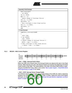
The following example shows how interrupts are moved.
59
8018A–AVR–03/06

 ATMEL [ ATMEL ]