10. Interrupts
This section describes the specifics of the interrupt handling as performed in ATmega169P. For
a general explanation of the AVR interrupt handling, refer to ”Reset and Interrupt Handling” on
page 16.
10.1 Interrupt Vectors in ATmega169P
Table 10-1. Reset and Interrupt Vectors
Vector Program
No.
Address(2)
Source
Interrupt Definition
External Pin, Power-on Reset, Brown-out Reset,
Watchdog Reset, and JTAG AVR Reset
1
0x0000(1)
RESET
2
0x0002
0x0004
0x0006
0x0008
0x000A
0x000C
0x000E
0x0010
0x0012
0x0014
0x0016
0x0018
0x001A
0x001C
0x001E
0x0020
0x0022
0x0024
0x0026
0x0028
0x002A
0x002C
INT0
External Interrupt Request 0
Pin Change Interrupt Request 0
Pin Change Interrupt Request 1
Timer/Counter2 Compare Match
Timer/Counter2 Overflow
Timer/Counter1 Capture Event
Timer/Counter1 Compare Match A
Timer/Counter1 Compare Match B
Timer/Counter1 Overflow
Timer/Counter0 Compare Match
Timer/Counter0 Overflow
SPI Serial Transfer Complete
USART0, Rx Complete
3
PCINT0
4
PCINT1
5
TIMER2 COMP
TIMER2 OVF
TIMER1 CAPT
TIMER1 COMPA
TIMER1 COMPB
TIMER1 OVF
TIMER0 COMP
TIMER0 OVF
SPI, STC
6
7
8
9
10
11
12
13
14
15
16
17
18
19
20
21
22
23
USART, RX
USART, UDREn
USART, TX
USI START
USI OVERFLOW
ANALOG COMP
ADC
USART0 Data Register Empty
USART0, Tx Complete
USI Start Condition
USI Overflow
Analog Comparator
ADC Conversion Complete
EEPROM Ready
EE READY
SPM READY
LCD
Store Program Memory Ready
LCD Start of Frame
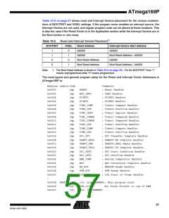
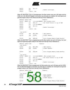
Notes: 1. When the BOOTRST Fuse is programmed, the device will jump to the Boot Loader address at
reset, see ”Boot Loader Support – Read-While-Write Self-Programming” on page 279.
2. When the IVSEL bit in MCUCR is set, Interrupt Vectors will be moved to the start of the Boot
Flash Section. The address of each Interrupt Vector will then be the address in this table
added to the start address of the Boot Flash Section.
56
ATmega169P
8018A–AVR–03/06

 ATMEL [ ATMEL ]