7.8
Timer/Counter Oscillator
ATmega169P uses the same crystal oscillator for Low-frequency Oscillator and Timer/Counter
Oscillator. See ”Low-frequency Crystal Oscillator” on page 33 for details on the oscillator and
crystal requirements.
ATmega169P share the Timer/Counter Oscillator Pins (TOSC1 and TOSC2) with XTAL1 and
XTAL2. When using the Timer/Counter Oscillator, the system clock needs to be four times the
oscillator frequency. Due to this and the pin sharing, the Timer/Counter Oscillator can only be
used when the Calibrated Internal RC Oscillator is selected as system clock source.
Applying an external clock source to TOSC1 can be done if EXTCLK in the ASSR Register is
written to logic one. See ”Asynchronous operation of the Timer/Counter” on page 150 for further
description on selecting external clock as input instead of a 32.768 kHz watch crystal.
7.9
Clock Output Buffer
When the CKOUT Fuse is programmed, the system Clock will be output on CLKO. This mode is
suitable when chip clock is used to drive other circuits on the system. The clock will be output
also during reset and the normal operation of I/O pin will be overridden when the fuse is pro-
grammed. Any clock source, including internal RC Oscillator, can be selected when CLKO
serves as clock output. If the System Clock Prescaler is used, it is the divided system clock that
is output when the CKOUT Fuse is programmed.
7.10 System Clock Prescaler
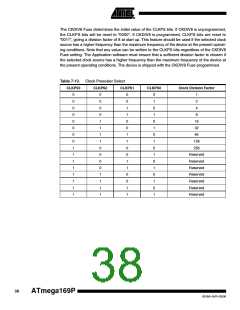
The ATmega169P system clock can be divided by setting the ”CLKPR – Clock Prescale Regis-
ter” on page 37. This feature can be used to decrease the system clock frequency and power
consumption when the requirement for processing power is low. This can be used with all clock
source options, and it will affect the clock frequency of the CPU and all synchronous peripherals.
clkI/O, clkADC, clkCPU, and clkFLASH are divided by a factor as shown in Table 7-13.
When switching between prescaler settings, the System Clock Prescaler ensures that no
glitches occur in the clock system and that no intermediate frequency is higher than neither the
clock frequency corresponding to the previous setting, nor the clock frequency corresponding to
the new setting.
The ripple counter that implements the prescaler runs at the frequency of the undivided clock,
which may be faster than the CPU’s clock frequency. Hence, it is not possible to determine the
state of the prescaler – even if it were readable, and the exact time it takes to switch from one
clock division to another cannot be exactly predicted. From the time the CLKPS values are writ-
ten, it takes between T1 + T2 and T1 + 2*T2 before the new clock frequency is active. In this
interval, 2 active clock edges are produced. Here, T1 is the previous clock period, and T2 is the
period corresponding to the new prescaler setting.
To avoid unintentional changes of clock frequency, a special write procedure must be followed
to change the CLKPS bits:
1. Write the Clock Prescaler Change Enable (CLKPCE) bit to one and all other bits in
CLKPR to zero.
2. Within four cycles, write the desired value to CLKPS while writing a zero to CLKPCE.
Interrupts must be disabled when changing prescaler setting to make sure the write procedure is
not interrupted.
36
ATmega169P
8018A–AVR–03/06

 ATMEL [ ATMEL ]