7.5
Crystal Oscillator
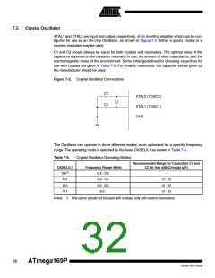
XTAL1 and XTAL2 are input and output, respectively, of an inverting amplifier which can be con-
figured for use as an On-chip Oscillator, as shown in Figure 7-2. Either a quartz crystal or a
ceramic resonator may be used.
C1 and C2 should always be equal for both crystals and resonators. The optimal value of the
capacitors depends on the crystal or resonator in use, the amount of stray capacitance, and the
electromagnetic noise of the environment. Some initial guidelines for choosing capacitors for
use with crystals are given in Table 7-5. For ceramic resonators, the capacitor values given by
the manufacturer should be used.
Figure 7-2. Crystal Oscillator Connections
C2
XTAL2 (TOSC2)
C1
XTAL1 (TOSC1)
GND
The Oscillator can operate in three different modes, each optimized for a specific frequency
range. The operating mode is selected by the fuses CKSEL3:1 as shown in Table 7-5.
Table 7-5.
Crystal Oscillator Operating Modes
Recommended Range for Capacitors C1 and
C2 for Use with Crystals (pF)
CKSEL3:1
100(1)
101
Frequency Range (MHz)
0.4 - 0.9
0.9 - 3.0
3.0 - 8.0
8.0 -
–
12 - 22
12 - 22
12 - 22
110
111
Notes: 1. This option should not be used with crystals, only with ceramic resonators.
32
ATmega169P
8018A–AVR–03/06

 ATMEL [ ATMEL ]