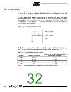
Figure 7-3. Crystal Oscillator Connections
TOSC2 (XTAL2)
TOSC1 (XTAL1)
Table 7-8.
Low-frequency Crystal Oscillator Internal load Capacitance
Min. (pF)
TBD
Typ. (pF)
Max. (pF)
6
TBD
Crystals specifying load capacitance (CL) higher than 6 pF, require external capacitors applied
as described in Figure 7-2 on page 32.
To find suitable load capacitance for a 32.768 kHz crystal, please consult the crystal datasheet.
The Low-frequency Crystal Oscillator must be selected by setting the CKSEL Fuses to “0110” or
“0111” as shown in Table 7-10. Start-up times are determined by the SUT Fuses as shown in
Table 7-9..
Table 7-9.
Start-up Times for the Low-frequency Crystal Oscillator Clock Selection
SUT1..0
00
Additional Delay from Reset (VCC = 5.0V) Recommended Usage
TBD
TBD
TBD
Fast rising power or BOD enabled
Slowly rising power
01
10
Stable frequency at start-up
11
Reserved
Table 7-10. Start-up Times for the Low-frequency Crystal Oscillator Clock Selection
Start-up Time from
CKSEL3..0
0110(1)
Power-down and Power-save
Recommended Usage
TBD
TBD
0111
Stable frequency at start-up
Note:
1. This option should only be used if frequency stability at start-up is not important for the
application
34
ATmega169P
8018A–AVR–03/06

 ATMEL [ ATMEL ]