ATmega169P
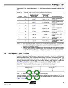
The CKSEL0 Fuse together with the SUT1..0 Fuses select the start-up times as shown in Table
7-6.
Table 7-6.
Start-up Times for the Crystal Oscillator Clock Selection
Start-up Time from
Power-down and
Power-save
Additional Delay
from Reset
CKSEL0
SUT1:0
(VCC = 5.0V)
Recommended Usage
Ceramic resonator, fast
rising power
0
00
258 CK(1)
258 CK(1)
1K CK(2)
1K CK(2)
1K CK(2)
16K CK
16K CK
16K CK
14CK + 4.1 ms
14CK + 65 ms
14CK
Ceramic resonator, slowly
rising power
0
0
0
1
1
1
1
01
10
11
00
01
10
11
Ceramic resonator, BOD
enabled
Ceramic resonator, fast
rising power
14CK + 4.1 ms
14CK + 65 ms
14CK
Ceramic resonator, slowly
rising power
Crystal Oscillator, BOD
enabled
Crystal Oscillator, fast
rising power
14CK + 4.1 ms
14CK + 65 ms
Crystal Oscillator, slowly
rising power
Notes: 1. These options should only be used when not operating close to the maximum frequency of the
device, and only if frequency stability at start-up is not important for the application. These
options are not suitable for crystals.
2. These options are intended for use with ceramic resonators and will ensure frequency stability
at start-up. They can also be used with crystals when not operating close to the maximum fre-
quency of the device, and if frequency stability at start-up is not important for the application.
7.6
Low-frequency Crystal Oscillator
The Low-frequency Crystal Oscillator is optimized for use with a 32.768 kHz watch crystal.
When selecting crystals, load capasitance and crystal’s Equivalent Series Resistance, ESR
must be taken into consideration. Both values are specified by the crystal vendor. ATmega169P
oscillator is optimized for very low power consumption, and thus when selecting crystals, see
Table 7-7 on page 33 for maximum ESR recommendations on 12.5 pF and 6 pF crystals
Table 7-7.
Maximum ESR Recommendation for 32.768 kHz Watch Crystal
Crystal CL (pF)
Max ESR [kΩ](1)
6
60
20
12.5
Note:
1. Maximum ESR is typical value based on characterization
The Low-frequency Crystal Oscillator provides an internal load capacitance of typical 6 pF. Crys-
tals with recommended 6 pF load capacitance can be without external capacitors as shown in
Figure 7-3 on page 34.
33
8018A–AVR–03/06

 ATMEL [ ATMEL ]