ATmega169P
8. Power Management and Sleep Modes
Sleep modes enable the application to shut down unused modules in the MCU, thereby saving-
power. The AVR provides various sleep modes allowing the user to tailor the power
consumption to the application’s requirements.
8.1
Sleep Modes
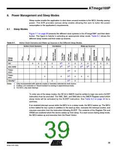
Figure 7-1 on page 29 presents the different clock systems in the ATmega169P, and their distri-
bution. The figure is helpful in selecting an appropriate sleep mode. Table 8-1 shows the
different sleep modes and their wake up sources.
Table 8-1.
Active Clock Domains and Wake-up Sources in the Different Sleep Modes.
Active Clock Domains Oscillators Wake-up Sources
Sleep
Mode
Idle
X
X
X
X
X
X
X(2)
X(2)
X
X
X
X
X
X
X
X
X
X
ADC NRM
X
X(3)
X(2)
X(2)
Power-
down
X(3)
X
Power-
save
X
X
X(3)
X(3)
X
X
X
X
Standby(1)
X
Notes: 1. Only recommended with external crystal or resonator selected as clock source.
2. If either LCD controller or Timer/Counter2 is running in asynchronous mode.
3. For INT0, only level interrupt.
To enter any of the sleep modes, the SE bit in SMCR must be written to logic one and a SLEEP
instruction must be executed. The SM2, SM1, and SM0 bits in the SMCR Register select which
sleep mode will be activated by the SLEEP instruction. See Table 8-2 on page 44 for a
summary.
If an enabled interrupt occurs while the MCU is in a sleep mode, the MCU wakes up. The MCU
is then halted for four cycles in addition to the start-up time, executes the interrupt routine, and
resumes execution from the instruction following SLEEP. The contents of the Register File and
SRAM are unaltered when the device wakes up from sleep. If a reset occurs during sleep mode,
the MCU wakes up and executes from the Reset Vector.
39
8018A–AVR–03/06

 ATMEL [ ATMEL ]