ATmega169P
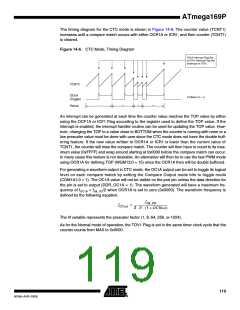
The timing diagram for the CTC mode is shown in Figure 14-6. The counter value (TCNT1)
increases until a compare match occurs with either OCR1A or ICR1, and then counter (TCNT1)
is cleared.
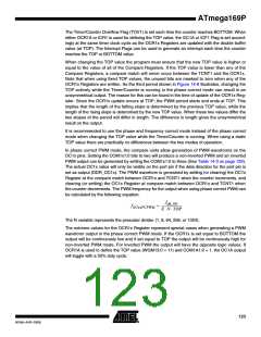
Figure 14-6. CTC Mode, Timing Diagram
OCnA Interrupt Flag Set
or ICFn Interrupt Flag Set
(Interrupt on TOP)
TCNTn
OCnA
(Toggle)
(COMnA1:0 = 1)
1
2
3
4
Period
An interrupt can be generated at each time the counter value reaches the TOP value by either
using the OCF1A or ICF1 Flag according to the register used to define the TOP value. If the
interrupt is enabled, the interrupt handler routine can be used for updating the TOP value. How-
ever, changing the TOP to a value close to BOTTOM when the counter is running with none or a
low prescaler value must be done with care since the CTC mode does not have the double buff-
ering feature. If the new value written to OCR1A or ICR1 is lower than the current value of
TCNT1, the counter will miss the compare match. The counter will then have to count to its max-
imum value (0xFFFF) and wrap around starting at 0x0000 before the compare match can occur.
In many cases this feature is not desirable. An alternative will then be to use the fast PWM mode
using OCR1A for defining TOP (WGM13:0 = 15) since the OCR1A then will be double buffered.
For generating a waveform output in CTC mode, the OC1A output can be set to toggle its logical
level on each compare match by setting the Compare Output mode bits to toggle mode
(COM1A1:0 = 1). The OC1A value will not be visible on the port pin unless the data direction for
the pin is set to output (DDR_OC1A = 1). The waveform generated will have a maximum fre-
quency of fOC A = fclk_I/O/2 when OCR1A is set to zero (0x0000). The waveform frequency is
1
defined by the following equation:
f
clk_I/O
f
= --------------------------------------------------
OCnA
2 ⋅ N ⋅ (1 + OCRnA)
The N variable represents the prescaler factor (1, 8, 64, 256, or 1024).
As for the Normal mode of operation, the TOV1 Flag is set in the same timer clock cycle that the
counter counts from MAX to 0x0000.
119
8018A–AVR–03/06

 ATMEL [ ATMEL ]