14.8.3
Fast PWM Mode
The fast Pulse Width Modulation or fast PWM mode (WGM13:0 = 5, 6, 7, 14, or 15) provides a
high frequency PWM waveform generation option. The fast PWM differs from the other PWM
options by its single-slope operation. The counter counts from BOTTOM to TOP then restarts
from BOTTOM. In non-inverting Compare Output mode, the Output Compare (OC1x) is set on
the compare match between TCNT1 and OCR1x, and cleared at TOP. In inverting Compare
Output mode output is cleared on compare match and set at TOP. Due to the single-slope oper-
ation, the operating frequency of the fast PWM mode can be twice as high as the phase correct
and phase and frequency correct PWM modes that use dual-slope operation. This high fre-
quency makes the fast PWM mode well suited for power regulation, rectification, and DAC
applications. High frequency allows physically small sized external components (coils, capaci-
tors), hence reduces total system cost.
The PWM resolution for fast PWM can be fixed to 8-, 9-, or 10-bit, or defined by either ICR1 or
OCR1A. The minimum resolution allowed is 2-bit (ICR1 or OCR1A set to 0x0003), and the max-
imum resolution is 16-bit (ICR1 or OCR1A set to MAX). The PWM resolution in bits can be
calculated by using the following equation:
log(TOP + 1)
R
= ----------------------------------
FPWM
log(2)
In fast PWM mode the counter is incremented until the counter value matches either one of the
fixed values 0x00FF, 0x01FF, or 0x03FF (WGM13:0 = 5, 6, or 7), the value in ICR1 (WGM13:0 =
14), or the value in OCR1A (WGM13:0 = 15). The counter is then cleared at the following timer
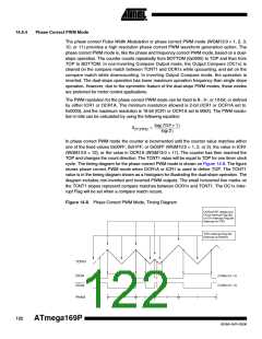
clock cycle. The timing diagram for the fast PWM mode is shown in Figure 14-7. The figure
shows fast PWM mode when OCR1A or ICR1 is used to define TOP. The TCNT1 value is in the
timing diagram shown as a histogram for illustrating the single-slope operation. The diagram
includes non-inverted and inverted PWM outputs. The small horizontal line marks on the TCNT1
slopes represent compare matches between OCR1x and TCNT1. The OC1x Interrupt Flag will
be set when a compare match occurs.
Figure 14-7. Fast PWM Mode, Timing Diagram
OCRnx / TOP Update
and TOVn Interrupt Flag
Set and OCnA Interrupt
Flag Set or ICFn
Interrupt Flag Set
(Interrupt on TOP)
TCNTn
(COMnx1:0 = 2)
OCnx
(COMnx1:0 = 3)
OCnx
1
2
3
4
5
6
7
8
Period
The Timer/Counter Overflow Flag (TOV1) is set each time the counter reaches TOP. In addition
the OC1A or ICF1 Flag is set at the same timer clock cycle as TOV1 is set when either OCR1A
120
ATmega169P
8018A–AVR–03/06

 ATMEL [ ATMEL ]