ATmega640/1280/1281/2560/2561
9. External Memory Interface
With all the features the External Memory Interface provides, it is well suited to operate as an
interface to memory devices such as External SRAM and Flash, and peripherals such as LCD-
display, A/D, and D/A. The main features are:
• Four different wait-state settings (including no wait-state).
• Independent wait-state setting for different External Memory sectors (configurable sector size)
• The number of bits dedicated to address high byte is selectable
• Bus keepers on data lines to minimize current consumption (optional)
9.1
Overview
When the eXternal MEMory (XMEM) is enabled, address space outside the internal SRAM
becomes available using the dedicated External Memory pins (see Figure 1-3 on page 4, Table
13-3 on page 78, Table 13-9 on page 82, and Table 13-20 on page 90). The memory configura-
tion is shown in Figure 9-1.
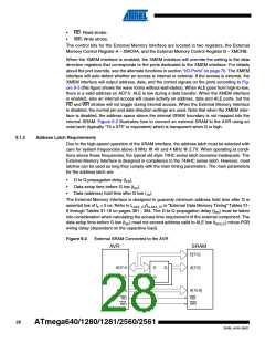
Figure 9-1. External Memory with Sector Select
Memory Configuration A
0x0000
Internal memory
0x21FF
0x2200
Lower sector
SRW01
SRW00
SRL[2..0]
External Memory
Upper sector
(0-60K x 8)
SRW11
SRW10
0xFFFF
9.1.1
Using the External Memory Interface
The interface consists of:
•
AD7:0: Multiplexed low-order address bus and data bus.
• A15:8: High-order address bus (configurable number of bits).
•
ALE: Address latch enable.
27
2549L–AVR–08/07

 ATMEL [ ATMEL ]