The mechanisms for reading TCNT2, OCR2A, OCR2B, TCCR2A and TCCR2B are different.
When reading TCNT2, the actual timer value is read. When reading OCR2A, OCR2B, TCCR2A
and TCCR2B the value in the temporary storage register is read.
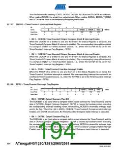
20.10.7 TIMSK2 – Timer/Counter2 Interrupt Mask Register
Bit
(0x70)
7
6
5
4
–
3
–
2
OCIE2B
R/W
0
1
OCIE2A
R/W
0
0
TOIE2
R/W
0
–
–
–
TIMSK2
Read/Write
R
0
R
0
R
0
R
0
R
0
Initial Value
• Bit 2 – OCIE2B: Timer/Counter2 Output Compare Match B Interrupt Enable
When the OCIE2B bit is written to one and the I-bit in the Status Register is set (one), the
Timer/Counter2 Compare Match B interrupt is enabled. The corresponding interrupt is executed
if a compare match in Timer/Counter2 occurs, i.e., when the OCF2B bit is set in the
Timer/Counter 2 Interrupt Flag Register – TIFR2.
• Bit 1 – OCIE2A: Timer/Counter2 Output Compare Match A Interrupt Enable
When the OCIE2A bit is written to one and the I-bit in the Status Register is set (one), the
Timer/Counter2 Compare Match A interrupt is enabled. The corresponding interrupt is executed
if a compare match in Timer/Counter2 occurs, i.e., when the OCF2A bit is set in the
Timer/Counter 2 Interrupt Flag Register – TIFR2.
• Bit 0 – TOIE2: Timer/Counter2 Overflow Interrupt Enable
When the TOIE2 bit is written to one and the I-bit in the Status Register is set (one), the
Timer/Counter2 Overflow interrupt is enabled. The corresponding interrupt is executed if an
overflow in Timer/Counter2 occurs, i.e., when the TOV2 bit is set in the Timer/Counter2 Interrupt
Flag Register – TIFR2.
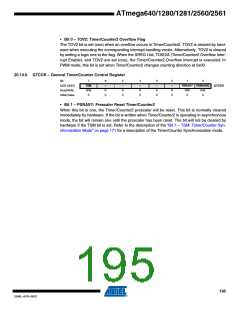
20.10.8 TIFR2 – Timer/Counter2 Interrupt Flag Register
Bit
0x17 (0x37)
7
6
5
–
4
–
3
–
2
OCF2B
R/W
0
1
OCF2A
R/W
0
0
TOV2
R/W
0
–
–
TIFR2
Read/Write
R
0
R
0
R
0
R
0
R
0
Initial Value
• Bit 2 – OCF2B: Output Compare Flag 2 B
The OCF2B bit is set (one) when a compare match occurs between the Timer/Counter2 and the
data in OCR2B – Output Compare Register2. OCF2B is cleared by hardware when executing
the corresponding interrupt handling vector. Alternatively, OCF2B is cleared by writing a logic
one to the flag. When the I-bit in SREG, OCIE2B (Timer/Counter2 Compare match Interrupt
Enable), and OCF2B are set (one), the Timer/Counter2 Compare match Interrupt is executed.
• Bit 1 – OCF2A: Output Compare Flag 2 A
The OCF2A bit is set (one) when a compare match occurs between the Timer/Counter2 and the
data in OCR2A – Output Compare Register2. OCF2A is cleared by hardware when executing
the corresponding interrupt handling vector. Alternatively, OCF2A is cleared by writing a logic
one to the flag. When the I-bit in SREG, OCIE2A (Timer/Counter2 Compare match Interrupt
Enable), and OCF2A are set (one), the Timer/Counter2 Compare match Interrupt is executed.
194
ATmega640/1280/1281/2560/2561
2549L–AVR–08/07

 ATMEL [ ATMEL ]