ATmega640/1280/1281/2560/2561
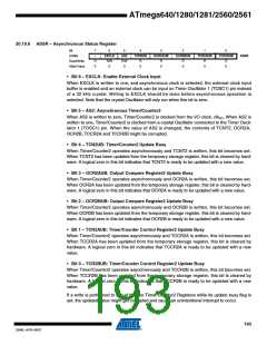
20.10.6 ASSR – Asynchronous Status Register
Bit
7
–
6
EXCLK
R/W
0
5
4
3
2
1
0
(0xB6)
AS2
R/W
0
TCN2UB
OCR2AUB
OCR2BUB
TCR2AUB
TCR2BUB
ASSR
Read/Write
Initial Value
R
0
R
0
R
0
R
0
R
0
R
0
• Bit 6 – EXCLK: Enable External Clock Input
When EXCLK is written to one, and asynchronous clock is selected, the external clock input
buffer is enabled and an external clock can be input on Timer Oscillator 1 (TOSC1) pin instead
of a 32 kHz crystal. Writing to EXCLK should be done before asynchronous operation is
selected. Note that the crystal Oscillator will only run when this bit is zero.
• Bit 5 – AS2: Asynchronous Timer/Counter2
When AS2 is written to zero, Timer/Counter2 is clocked from the I/O clock, clkI/O. When AS2 is
written to one, Timer/Counter2 is clocked from a crystal Oscillator connected to the Timer Oscil-
lator 1 (TOSC1) pin. When the value of AS2 is changed, the contents of TCNT2, OCR2A,
OCR2B, TCCR2A and TCCR2B might be corrupted.
• Bit 4 – TCN2UB: Timer/Counter2 Update Busy
When Timer/Counter2 operates asynchronously and TCNT2 is written, this bit becomes set.
When TCNT2 has been updated from the temporary storage register, this bit is cleared by hard-
ware. A logical zero in this bit indicates that TCNT2 is ready to be updated with a new value.
• Bit 3 – OCR2AUB: Output Compare Register2 Update Busy
When Timer/Counter2 operates asynchronously and OCR2A is written, this bit becomes set.
When OCR2A has been updated from the temporary storage register, this bit is cleared by hard-
ware. A logical zero in this bit indicates that OCR2A is ready to be updated with a new value.
• Bit 2 – OCR2BUB: Output Compare Register2 Update Busy
When Timer/Counter2 operates asynchronously and OCR2B is written, this bit becomes set.
When OCR2B has been updated from the temporary storage register, this bit is cleared by hard-
ware. A logical zero in this bit indicates that OCR2B is ready to be updated with a new value.
• Bit 1 – TCR2AUB: Timer/Counter Control Register2 Update Busy
When Timer/Counter2 operates asynchronously and TCCR2A is written, this bit becomes set.
When TCCR2A has been updated from the temporary storage register, this bit is cleared by
hardware. A logical zero in this bit indicates that TCCR2A is ready to be updated with a new
value.
• Bit 0 – TCR2BUB: Timer/Counter Control Register2 Update Busy
When Timer/Counter2 operates asynchronously and TCCR2B is written, this bit becomes set.
When TCCR2B has been updated from the temporary storage register, this bit is cleared by
hardware. A logical zero in this bit indicates that TCCR2B is ready to be updated with a new
value.
If a write is performed to any of the five Timer/Counter2 Registers while its update busy flag is
set, the updated value might get corrupted and cause an unintentional interrupt to occur.
193
2549L–AVR–08/07

 ATMEL [ ATMEL ]