ATmega640/1280/1281/2560/2561
Address Labels Code
.org 0x0002
Comments
0x00002
0x00004
...
jmp
jmp
...
jmp
EXT_INT0
EXT_INT1
...
; IRQ0 Handler
; IRQ1 Handler
;
0x00070
;
USART3_TXC
; USART3 TX Complete Handler
.org 0x1F000
0x1F000 RESET: ldi
r16,high(RAMEND); Main program start
0x1F001
0x1F002
out
ldi
SPH,r16
; Set Stack Pointer to top of RAM
r16,low(RAMEND)
SPL,r16
0x1F003
0x1F004
out
sei
; Enable interrupts
0x1F005
<instr> xxx
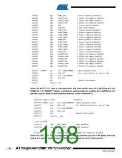
When the BOOTRST Fuse is programmed, the Boot section size set to 8K bytes and the IVSEL
bit in the MCUCR Register is set before any interrupts are enabled, the most typical and general
program setup for the Reset and Interrupt Vector Addresses is:
Address Labels Code
Comments
;
.org 0x1F000
0x1F000
0x1F002
jmp
jmp
RESET
EXT_INT0
; Reset handler
; IRQ0 Handler
0x1F004
...
jmp
...
jmp
EXT_INT1
...
; IRQ1 Handler
;
0x1F070
;
USART3_TXC
; USART3 TX Complete Handler
0x1F072 RESET: ldi
r16,high(RAMEND) ; Main program start
0x1F073
0x1F074
out
ldi
SPH,r16
; Set Stack Pointer to top of RAM
r16,low(RAMEND)
SPL,r16
0x1F075
0x1F076
out
sei
; Enable interrupts
0x1FO77
<instr> xxx
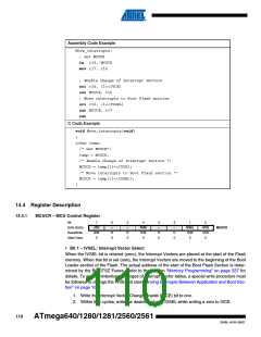
14.3 Moving Interrupts Between Application and Boot Section
The MCU Control Register controls the placement of the Interrupt Vector table, see Code Exam-
ple below. For more details, see “Reset and Interrupt Handling” on page 17.
109
2549L–AVR–08/07

 ATMEL [ ATMEL ]